


65
Filter Service Hours
This refers to the timer set for the Dirty Filter Alarm.
After the number of runtime hours set on this point is
exceeded the corresponding alarm will be generated, and
must be manually cleared on the alarm reset screen after
the maintenance has been completed. The timer will then
begin counting its runtime again for the next maintenance
interval.
Factory Default = 600 hr
NOTE
: Setting this configuration timer to 0, disables the
alarm.
Supply Fan Service Hours
This refers to the timer set for the Supply Fan Runtime
Alarm. After the number of runtime hours set on this point
is exceeded the corresponding alarm will be generated,
and must be manually cleared on the alarm reset screen
after the maintenance has been completed. The timer will
then begin counting its runtime again for the next
maintenance interval.
Factory Default = 0 hr
NOTE
: Setting this configuration timer to 0, disables the
alarm.
Compressor1 Service Hours
This refers to the timer set for the Compressor 1 Runtime
Alarm. After the number of runtime hours set on this point
is exceeded the corresponding alarm will be generated,
and must be manually cleared on the alarm reset screen
after the maintenance has been completed. The timer will
then begin counting its runtime again for the next
maintenance interval.
Factory Default = 0 hr
NOTE
: Setting this configuration timer to 0, disables the
alarm.
Compressor2 Service Hours
This refers to the timer set for the Compressor 2 Runtime
Alarm. After the number of hours set on this point is
exceeded the corresponding alarm will be generated, and
must be manually cleared on the alarm rest screen after
the maintenance has been completed. The timer will then
begin counting its runtime again for the next maintenance
interval
Factory Default = 0 hr
NOTE
: Setting this configuration timer to 0, disables the
alarm.
Cooling
Number of Compressor Stages
This refers to the number of mechanical cooling stages
available on a specific unit. Set this point to “One Stage”
if there is one compressor in the specific unit, set to “Two
Stage” if there are two compressors in the unit, and set to
“None” if economizer cooling ONLY is desired.
Factory Default = One Stage for 1 compressor units
Two Stage for 2 compressor units
Cooling/Econ SAT Low Setpt
The supply air temperature must remain above this value
to allow cooling with the economizer and/or compressors.
There is 5
_
F plus and minus deadband to this point. If the
SAT falls below this value during cooling, all compressors
will be staged off. The economizer will start to ramp
down to minimum position when the SAT = this
configu5
_
F.
Factory Default = 50
_
F
Range = 45--75
_
F
Cooling Lockout Temp
This defines the minimum outdoor air temperature that
cooling mode can be enabled and run. If the OAT falls
below this threshold during cooling, then compressor
cooling will not be allowed.
Factory Default = 45
_
F
Range = 0--65
_
F
Heating
Heating SAT High Setpt
The supply air temperature must remain below this value
to allow heating. There is 5
_
F plus and minus deadband to
this point. If the SAT rises above this value during heating
the heat stages will begin to decrease until the SAT has
dropped below this value.
Factory Default = 120
_
F
Range = 95--150
_
F
Heating Lockout Temp
This defines the maximum outdoor air temperature that
heating mode can be enabled and run. If the OAT rises
above this threshold during heating, then heating will not
be allowed.
Factory Default = 65
_
F
Range = 49--95
_
F
Inputs
NOTE
:
For installation of inputs and field installed
accessories, refer to the appropriate sections.
Input 3
This input is a discrete input and can be configured to be
one of five different inputs: No Function, Compressor
Safety, Fan Status, Filter Status, or Remote Occupancy.
This input can also be configured to be either Normally
Open (N/O) or Normally Closed (N/C). Input 3 is factory
wired to pin J1--2. Field accessories get wired to its
parallel pin J5--5. Do not connect inputs to both locations,
one function per input.
Factory Default = Compressor Safety and N/O
NOTE
: Compressor Safety input comes from the CLO
board. J1--2 is always factory wired to TB1--8 (X) terminal
on the unit. If the unit has a CLO board, do not configure
input 3 for anything but Compressor Safety.
580J
Summary of Contents for 580J*08--14D
Page 10: ...10 COOLING CHARGING CHARTS C09221 Fig 10 Cooling Charging Charts 08D F Both Circuits 580J ...
Page 11: ...11 COOLING CHARGING CHARTS C09222 Fig 11 Cooling Charging Charts 12D F Both Circuits 580J ...
Page 36: ...36 C07129 Fig 42 RTU MP Multi Protocol Control Board 580J ...
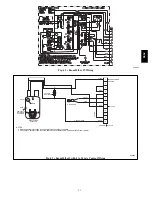
Page 37: ...37 C09163 Fig 43 Typical RTU MP System Control Wiring Diagram 580J ...
Page 60: ...60 C09156 Fig 73 580J Typical Unit Wiring Diagram Power 08D F 208 230 3 60 580J ...
Page 61: ...61 C09157 Fig 74 580J Typical Unit Wiring Diagram Control 08 12D F 208 230 3 60 580J ...
Page 84: ...84 580J ...


