


59
5. Turn the DCV setpoint potentiometer CW until the
DCV LED turns off. The DCV LED should turn off
when the potentiometer is approximately 9--v. The
actuator should drive fully closed.
6. Turn the DCV and Exhaust potentiometers CCW until
the Exhaust LED turns on. The exhaust contacts will
close 30 to 120 seconds after the Exhaust LED turns
on.
7. Return EconoMi$er IV settings and wiring to normal
after completing troubleshooting.
DCV Minimum and Maximum Position
To check the DCV minimum and maximum position:
1. Make sure EconoMi$er IV preparation procedure has
been performed.
2. Connect a 9--v battery to AQ (positive node) and AQ1
(negative node). The DCV LED should turn on. The
actuator should drive to between 90 and 95% open.
3. Turn the DCV Maximum Position potentiometer to
midpoint. The actuator should drive to between 20
and 80% open.
4. Turn the DCV Maximum Position potentiometer to
fully CCW. The actuator should drive fully closed.
5. Turn the Minimum Position potentiometer to
midpoint. The actuator should drive to between 20
and 80% open.
6. Turn the Minimum Position Potentiometer fully CW.
The actuator should drive fully open.
7. Remove the jumper from TR and N. The actuator
should drive fully closed.
8. Return EconoMi$er IV settings and wiring to normal
after completing troubleshooting.
Supply--Air Sensor Input
To check supply--air sensor input:
1. Make sure EconoMi$er IV preparation procedure has
been performed.
2. Set the Enthalpy potentiometer to A. The Free Cool
LED turns on. The actuator should drive to between
20 and 80% open.
3. Remove the 5.6 kilo--ohm resistor and jumper T to
T1. The actuator should drive fully open.
4. Remove the jumper across T and T1. The actuator
should drive fully closed.
5. Return EconoMi$er IV settings and wiring to normal
after completing troubleshooting.
EconoMi$er IV Troubleshooting Completion
This procedure is used to return the EconoMi$er IV to
operation. No troubleshooting or testing is done by
performing the following procedure.
1. Disconnect power at TR and TR1.
2. Set enthalpy potentiometer to previous setting.
3. Set DCV maximum position potentiometer to
previous setting.
4. Set minimum position, DCV setpoint, and exhaust
potentiometers to previous settings.
5. Remove 620--ohm resistor from terminals SR and +.
6. Remove 1.2 kilo--ohm checkout resistor from
terminals SO and +. If used, reconnect sensor from
terminals SO and +.
7. Remove jumper from TR to N.
8. Remove jumper from TR to 1.
9. Remove 5.6 kilo--ohm resistor from T and T1.
Reconnect wires at T and T1.
10. Remove jumper from P to P1. Reconnect device at P
and P1.
11. Apply power (24 vac) to terminals TR and TR1.
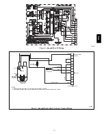
WIRING DIAGRAMS
See Fig. 73 and 74 for typical wiring diagrams.
580J
Summary of Contents for 580J*08--14D
Page 10: ...10 COOLING CHARGING CHARTS C09221 Fig 10 Cooling Charging Charts 08D F Both Circuits 580J ...
Page 11: ...11 COOLING CHARGING CHARTS C09222 Fig 11 Cooling Charging Charts 12D F Both Circuits 580J ...
Page 36: ...36 C07129 Fig 42 RTU MP Multi Protocol Control Board 580J ...
Page 37: ...37 C09163 Fig 43 Typical RTU MP System Control Wiring Diagram 580J ...
Page 60: ...60 C09156 Fig 73 580J Typical Unit Wiring Diagram Power 08D F 208 230 3 60 580J ...
Page 61: ...61 C09157 Fig 74 580J Typical Unit Wiring Diagram Control 08 12D F 208 230 3 60 580J ...
Page 84: ...84 580J ...


