


31
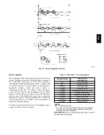
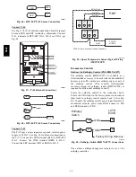
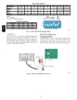
Red LED-Status
C08452
Fig. 40 -- Integrated Gas Control (IGC) Board
Table 10 – IGC Connections
TERMINAL LABEL
POINT DESCRIPTION
SENSOR LOCATION
TYPE OF I/O
CONNECTION
PIN NUMBER
INPUTS
RT, C
Input power from TRAN 1
control box
24 VAC
—
SS
Speed sensor
gas section
analog input
J1, 1-3
FS, T1
Flame sensor
gas section
switch input
—
W
Heat stage 1
LCTB
24 VAC
J2, 2
RS
Rollout switch
gas section
switch input
J2, 5-6
LS
Limit switch
fan section
switch input
J2, 7-8
CS
Centrifugal switch (not used)
—
switch input
J2, 9-10
OUTPUTS
L1, CM
Induced draft combustion motor
gas section
line VAC
IFO
Indoor fan
control box
relay
J2, 1
GV
Gas valve (heat stage 1)
gas section
relay
J2, 11-12
580J
Summary of Contents for 580J*08--14D
Page 10: ...10 COOLING CHARGING CHARTS C09221 Fig 10 Cooling Charging Charts 08D F Both Circuits 580J ...
Page 11: ...11 COOLING CHARGING CHARTS C09222 Fig 11 Cooling Charging Charts 12D F Both Circuits 580J ...
Page 36: ...36 C07129 Fig 42 RTU MP Multi Protocol Control Board 580J ...
Page 37: ...37 C09163 Fig 43 Typical RTU MP System Control Wiring Diagram 580J ...
Page 60: ...60 C09156 Fig 73 580J Typical Unit Wiring Diagram Power 08D F 208 230 3 60 580J ...
Page 61: ...61 C09157 Fig 74 580J Typical Unit Wiring Diagram Control 08 12D F 208 230 3 60 580J ...
Page 84: ...84 580J ...


