


46
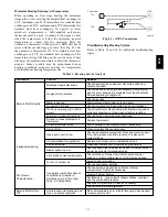
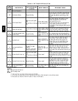
Table 18 – Troubleshooting Alarms
POINT NAME
BACnet
OBJECT
NAME
ACTION TAKEN BY
CONTROL
RESET
METHOD
PROBABLE CAUSE
Safety Chain Alarm
safety_chain
Alarm Generated
Immediate
Shutdown
Automatic
Over load Indoor Fan or Electric Heater overheat.
Fire Shutdown Alarm
fire_alarm
Alarm Generated
Immediate
Shutdown
Automatic
Smoke detected by smoke detector or
configuration incorrect
Space Temp Sensor
Failure
spt_alarm
Alarm Generated
Immediate
Shutdown
Automatic
Faulty, shorted, or open thermistor caused by
wiring error or loose connection.
SAT Sensor Alarm
sat_alarm
Alarm Generated
Immediate
Shutdown
Automatic
Faulty, shorted, or open thermistor caused by
wiring error or loose connection.
High Space Temp Alarm
spt_hi
Alarm Generated
Automatic
The space temperature has risen above the cool
setpoint by more than the desired amount.
Low Space Temp Alarm
spt_lo
Alarm Generated
Automatic
The space temperature has dropped below the
heat setpoint by more than the desired amount.
High Supply Air Temp
sat_hi
Alarm Generated
Automatic
SAT is greater then 160 degrees for more than 5
minutes.
Low Supply Air Temp
sat_lo
Alarm Generated
Automatic
The supply air temperature is below 35
_
F for
more than 5 minutes.
Supply Fan Failed to
Start
sf_fail
Alarm Generated
Immediately
disable Operation
Automatic
Tripped Circuit Breaker, Broken belt, Bad indoor
fan motor, Configuration incorrect, Bad fan status
switch.
Supply Fan in Hand
sf_hand
Alarm Generated
Ramp down
Operations
Automatic
Bad Fan Status Switch, Configuration incorrect.
Compressor Safety
Alarm
dx_compstat
Alarm Generated
Automatic
Compressor would not start.
Setpoint Slider Alarm
slide_alarm
Alarm Generated
Offset set to zero
Automatic
STO sensor is open or shorted for more then 5
seconds.
Dirty Filter Alarm
filter
Alarm Generated
Automatic/re
set timer
when
configured
with or
without
switch
Dirty Filter, supply fan run time exceeded, filter
switch configuration wrong.
Switch Configuration
Alarm
sw_cfg_alarm
Alarm Generated
Disable
misconfigured switch
functions
Configure
correctly
More than one binary input is configured for the
same purpose. More then one discrete input is
configured to provide the same function.
Misconfigured Analog
Input
an_cfg_alarm
Alarm Generated
Disable 4 selectable
analog inputs
Configure
correctly
More then one analog input is configured to
provide the same function.
OAT Sensor Alarm
oat_alarm
Alarm Generated
Economizer and Low
ambient DX cooling
lockout disabled.
Automatic
Faulty, shorted, or open thermistor caused by
wiring error or loose connection.
Space RH Sensor Alarm
sprh_alarm
Alarm Generated
Dehumidification
disabled
Automatic
Sensor reading is out of range. Bad sensor, bad
wiring, or sensor configured incorrectly.
Outdoor RH Sensor
Alarm
oarh_alarm
Alarm Generated
Automatic
Sensor reading is out of range. Bad sensor, bad
wiring, or sensor configured incorrectly.
High Space Humidity
sprh_hi
Alarm Generated
Automatic
IRH is greater then 70% for more then 10
minutes.
Low Space Humidity
sprh_lo
Alarm Generated
Automatic
IRH is less then 35% for more then 10 minutes.
IAQ Sensor Alarm
iaq_alarm
Alarm Generated
Disables IAQ
Operation
Economizer moves
to minimum position
Automatic
Sensor reading is out of range. Bad sensor, bad
wiring, or sensor configured incorrectly.
OAQ Sensor Alarm
oaq_alarm
Alarm Generated Set
OAQ to 400
Automatic
Sensor reading is out of range. Bad sensor, bad
wiring, or sensor configured incorrectly.
High Carbon Dioxide
Level
co2_hi
Alarm Generated
Automatic
CO2 reading is above 1200ppm.
Supply Fan Runtime
Alarm
sf_rntm
Alarm Generated
clear the
timer
Supply fan run time exceeded user defined limit.
Compressor 1 Runtime
Alarm
dx1_rntm
Alarm Generated
clear the
timer
Compressor run time limit is exceeded.
Compressor 2 Runtime
Alarm
dx2_rntm
Alarm Generated
clear the
timer
Compressor run time limit is exceeded.
580J
Summary of Contents for 580J*08--14D
Page 10: ...10 COOLING CHARGING CHARTS C09221 Fig 10 Cooling Charging Charts 08D F Both Circuits 580J ...
Page 11: ...11 COOLING CHARGING CHARTS C09222 Fig 11 Cooling Charging Charts 12D F Both Circuits 580J ...
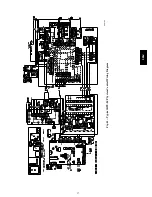
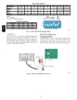
Page 36: ...36 C07129 Fig 42 RTU MP Multi Protocol Control Board 580J ...
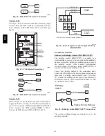
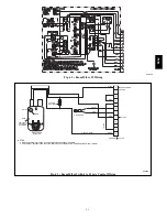
Page 37: ...37 C09163 Fig 43 Typical RTU MP System Control Wiring Diagram 580J ...
Page 60: ...60 C09156 Fig 73 580J Typical Unit Wiring Diagram Power 08D F 208 230 3 60 580J ...
Page 61: ...61 C09157 Fig 74 580J Typical Unit Wiring Diagram Control 08 12D F 208 230 3 60 580J ...
Page 84: ...84 580J ...


