


64
NOTE
: The default value for the evaporator--fan motor
on/off delay is 45 seconds. The Integrated Gas Unit
Controller (IGC) modifies this value when abnormal limit
switch cycles occur. Based upon unit operating conditions,
the on delay can be reduced to 0 seconds and the off delay
can be extended to 180 seconds.
If the limit switch trips at the start of the heating cycle
during the evaporator on delay, the time period of the on
delay for the next cycle will be 5 seconds less than the
time at which the switch tripped. (Example: If the limit
switch trips at 30 seconds, the evaporator--fan on delay for
the next cycle will occur at 25 seconds.) To prevent
short--cycling, a 5--second reduction will only occur if a
minimum of 10 minutes has elapsed since the last call for
heating.
The evaporator--fan off delay can also be modified. Once
the call for heating has ended, there is a 10--minute period
during which the modification can occur. If the limit
switch trips during this period, the evaporator--fan off
delay will increase by 15 seconds. A maximum of 9 trips
can occur, extending the evaporator-fan off delay to 180
seconds.
To restore the original default value, reset the power to the
unit.
To shut off unit, set system selector switch at OFF
position. Resetting heating selector lever below room
temperature will temporarily shut unit off until space
temperature falls below thermostat setting.
Ventilation (Continuous Fan)
Set fan and system selector switches at ON and OFF
positions,
respectively.
Evaporator
fan
operates
continuously to provide constant air circulation. When the
evaporator-fan selector switch is turned to the OFF
position, there is a 30--second delay before the fan turns
off.
START--UP, RTU--MP CONTROL
Field Service Test, explained below, will assist in proper
start--up. Configuration of unit parameters, scheduling
options, and operation are also discussed in this section.
Field Service Test
The Field Service Test function can be used to verify
proper operation of compressors, heating stages, indoor
fan,
power
exhaust
fans,
economizer,
and
dehumidification. Use of Field Service Test is
recommended at initial system start up and during
troubleshooting. See RTU--MP Controls, Start--Up,
Operation, and Troubleshooting Instructions (Form
48--50H--T--2T), Appendix A for Field Service Test Mode
table.
Field Service Test mode has the following changes from
normal operation:
S
Outdoor air temperature limits for cooling circuits,
economizer, and heating are ignored.
S
Normal compressor time guards and other staging delays
are ignored.
S
The status of Alarms (except Fire and Safety chain) is
ignored but all alerts and alarms are still broadcasted on
the network.
Field Service Test can be turned ON/OFF at the unit
display or from the network. Once turned ON, other
entries may be made with the display or through the
network. To turn Field Service Test on, change the value
of Test Mode to ON, to turn Field Service Test off, change
the value of Test Mode to OFF.
NOTE
: Service Test mode is password protected when
accessing from the display. Depending on the unit model,
factory--installed options, and field--installed accessories,
some of the Field Service Test functions may not apply.
The independent outputs (IndpOutputs) submenu is used
to change output status for the supply fan, economizer,
and Power Exhaust. These independent outputs can
operate simultaneously with other Field Service Test
modes. All outputs return to normal operation when Field
Service Test is turned off.
The Cooling submenu is used to change output status for
the individual compressors and the dehumidification relay.
Compressor starts are not staggered. The fans and heating
service test outputs are reset to OFF for the cooling
service test. Indoor fans and outdoor fans are controlled
normally to maintain proper unit operation. All normal
cooling alarms and alerts are functional.
NOTE
: Circuit A is always operated with Circuit B due
to outdoor fan control on Circuit A. Always test Circuit A
first, and leave it on to test other Circuits.
The Heating submenu is used to change output status for
the individual heat stages, gas or electric. The fans and
cooling service test outputs are reset to OFF for the
heating service test. All normal heating alarms and alerts
are functional.
Configuration
The RTU--MP controller configuration points affect the
unit operation and/or control. Review and understand the
meaning and purpose of each configuration point before
changing it from the factory default value. The submenus
containing configuration points are as follows: Unit,
Cooling, Heating, Inputs, Economizer, IAQ, Clock--Set,
and User Password (USERPW). Each configuration point
is described below under its according submenu. See
RTU--MP
Controls,
Start--Up,
Operation,
and
Troubleshooting Instructions (Form 48--50H--T--2T),
Appendix for display tables.
Unit
Start Delay
This refers to the time delay the unit will wait after power
up before it pursues any specific operation.
Factory Default = 5 sec
Range = 0--600 sec
580J
Summary of Contents for 580J*08--14D
Page 10: ...10 COOLING CHARGING CHARTS C09221 Fig 10 Cooling Charging Charts 08D F Both Circuits 580J ...
Page 11: ...11 COOLING CHARGING CHARTS C09222 Fig 11 Cooling Charging Charts 12D F Both Circuits 580J ...
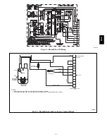
Page 36: ...36 C07129 Fig 42 RTU MP Multi Protocol Control Board 580J ...
Page 37: ...37 C09163 Fig 43 Typical RTU MP System Control Wiring Diagram 580J ...
Page 60: ...60 C09156 Fig 73 580J Typical Unit Wiring Diagram Power 08D F 208 230 3 60 580J ...
Page 61: ...61 C09157 Fig 74 580J Typical Unit Wiring Diagram Control 08 12D F 208 230 3 60 580J ...
Page 84: ...84 580J ...


