


38
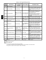
Table 15 – RTU--MP Controller Inputs and Outputs
POINT NAME
BACnet OBJECT
NAME
TYPE OF I/O
CONNECTION PIN
NUMBERS
INPUTS
Space Temperature Sensor
sptsens
AI (10K Thermistor)
J20---1, 2
Supply Air Temperature
sat
AI (10K Thermistor)
J2---1, 2
Local Outside Air Temperature Sensor
oatsens
AI (10K Thermistor)
J2---3, 4
Space Temperature Offset Pot
sptopot
AI (100K Potentiometer)
J20---3
Indoor Air Quality
iaq
AI (4---20 ma)
J4---2, 3
Outdoor Air Quality
oaq
AI (4---20 ma)
J4---5, 6
Safety Chain Feedback
safety
DI (24 VAC)
J1---9
Compressor Safety
compstat
DI (24 VAC)
J1---2
Fire Shutdown
firedown
DI (24 VAC)
J1---10
Enthalpy Switch
enthalpy
DI (24 VAC)
J2---6, 7
Humidistat Input Status
humstat
DI (24 VAC)
J5---7, 8
CONFIGURABLE INPUTS*
Space Relative Humidity
sprh
AI (4---20 ma)
J4---2,3 or J4---5,6
Outside Air Relative Humidity
oarh
AI (4---20 ma)
Supply Fan Status
fanstat
DI (24 VAC)
J5---1,2 or J5---3,4 or
J5 5,6 or J5---7,8
Filter Status
filtstat
DI (24 VAC)
Remote Occupancy Input
remocc
DI (24 VAC)
OUTPUTS
Economizer Commanded Position
econocmd
4---20ma
J2---5
Supply Fan Relay State
sf
DO Relay (24VAC , 1A)
J1---4
Compressor 1 Relay State
comp_1
DO Relay (24VAC , 1A)
J1---8
Compressor 2 Relay State
comp_2
DO Relay (24VAC , 1A)
J1---7
Heat Stage 1 Relay State
heat_1
DO Relay (24VAC , 1A)
J1---6
Heat Stage 2 Relay State
heat_2
DO Relay (24VAC , 1A)
J1---5
Power Exhaust Relay State
aux_2
DO Relay (24VAC , 1A)
J11---3
Dehumidification Relay State
humizer
DO Relay (24VAC, 1A)
J11---7, 8
LEGEND
AI
--- Analog Input
AO
--- Analog Output
DI
--- Discrete Input
DO
--- Discrete Output
* These inputs (if installed) take the place of the default input on the specific channel according to schematic.
Parallel pins J5---1 = J2---6, J5---3 = J1---10, J5---5 = J1---2 are used for field---installation.
Refer to the input configuration and accessory sections for more detail.
NOTE
: Refer to RTU--MP Controls, Start-Up, Operation,
and Troubleshooting Instructions (Form 48--50H--T--2T)
for complete configuration of RTU--MP, operating
sequences and troubleshooting information. Refer to
RTU--MP 3rd Party Integration Guide for details on
configuration and troubleshooting of connected networks.
Have a copy of these manuals available at unit start--up.
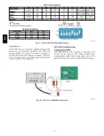
The RTU--MP controller requires the use of a Bryant
space sensor. A standard thermostat cannot be used with
the RTU--MP system.
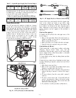
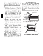
Supply Air Temperature (SAT) Sensor
On FIOP--equipped 580J unit, the unit is supplied with a
supply--air temperature (SAT) sensor (33ZCSENSAT).
This sensor is a tubular probe type, approx 6--inches (12.7
mm) in length. It is a nominal 10--k ohm thermistor. See
Table 16 for temperature--resistance characteristic.
The SAT is factory--wired. The SAT probe is wire--tied to
the supply--air opening (on the horizontal opening end) in
its shipping position. Remove the sensor for installation.
Re--position the sensor in the flange of the supply--air
opening or in the supply air duct (as required by local
codes). Drill or punch a 1/2--in. hole in the flange or duct.
Use two field--supplied, self--drilling screws to secure the
sensor probe in a horizontal orientation. (See Fig. 43.)
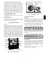
Outdoor Air Temperature (OAT) Sensor
The OAT is factory--mounted in the EconoMi$er 2 (FIOP
or accessory). It is a nominal 10k ohm thermistor attached
to an eyelet mounting ring. See Table 16 for
temperature--resistance characteristic.
580J
Summary of Contents for 580J*08--14D
Page 10: ...10 COOLING CHARGING CHARTS C09221 Fig 10 Cooling Charging Charts 08D F Both Circuits 580J ...
Page 11: ...11 COOLING CHARGING CHARTS C09222 Fig 11 Cooling Charging Charts 12D F Both Circuits 580J ...
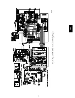
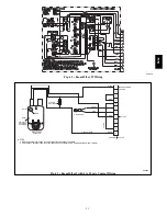
Page 36: ...36 C07129 Fig 42 RTU MP Multi Protocol Control Board 580J ...
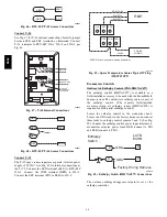
Page 37: ...37 C09163 Fig 43 Typical RTU MP System Control Wiring Diagram 580J ...
Page 60: ...60 C09156 Fig 73 580J Typical Unit Wiring Diagram Power 08D F 208 230 3 60 580J ...
Page 61: ...61 C09157 Fig 74 580J Typical Unit Wiring Diagram Control 08 12D F 208 230 3 60 580J ...
Page 84: ...84 580J ...


