


6
Changing the Fan Wheel Speed by Changing Pulleys
The horsepower rating of the belt is primarily dictated by
the pitch diameter of the smaller pulley in the drive
system (typically the motor pulley in these units). Do not
install a replacement motor pulley with a smaller pitch
diameter than provided on the original factory pulley.
Change fan wheel speed by changing the fan pulley
(larger pitch diameter to reduce wheel speed, smaller
pitch diameter to increase wheel speed) or select a new
system (both pulleys and matching belt(s).)
Before changing pulleys to increase fan wheel speed,
check the fan performance at the target speed and airflow
rate to determine new motor loading (bhp). Use the fan
performance tables or use the Packaged Rooftop Builder
software program. Confirm that the motor in this unit is
capable of operating at the new operating condition. Fan
shaft loading increases dramatically as wheel speed is
increased.
To reduce vibration, replace the motor’s adjustable pitch
pulley with a fixed pitch pulley (after the final airflow
balance adjustment). This will reduce the amount of
vibration generated by the motor/belt--drive system.
COOLING
UNIT OPERATION AND SAFETY HAZARD
Failure to follow this warning could cause personal
injury, death and/or equipment damage.
This system uses Puron
R
refrigerant which has higher
pressures than R--22 and other refrigerants. No other
refrigerant may be used in this system. Gauge set,
hoses, and recovery system must be designed to
handle Puron refrigerant. If unsure about equipment,
consult the equipment manufacturer.
!
WARNING
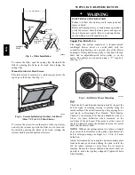
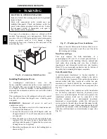
Condenser Coil
The condenser coil is new NOVATION Heat Exchanger
Technology. This is an all--aluminum construction with
louvered fins over single--depth crosstubes.
The
crosstubes have multiple small passages through which
the refrigerant passes from header to header on each end.
Tubes and fins are both aluminum construction.
Connection tube joints are copper. The coil may be
one--row or two--row. Two--row coils are spaced apart to
assist in cleaning. (See Fig. 8.)
TUBES
FINS
MANIFOLD
MICROCHANNELS
C07273
Fig. 8 -- NOVATION Heat Exchanger Coils
Evaporator Coil
The evaporator coil is traditional round--tube, plate--fin
technology.
Tube and fin construction is of various
optional materials and coatings (see Model Number
Format). Coils are multiple--row.
Coil Maintenance and Cleaning Recommendation
Routine cleaning of coil surfaces is essential to maintain
proper operation of the unit. Elimination of contamination
and removal of harmful residues will greatly increase the
life of the coil and extend the life of the unit. The
following maintenance and cleaning procedures are
recommended as part of the routine maintenance activities
to extend the life of the coil.
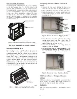
Remove Surface Loaded Fibers
Surface loaded fibers or dirt should be removed with a
vacuum cleaner. If a vacuum cleaner is not available, a
soft non--metallic bristle brush may be used. In either
case, the tool should be applied in the direction of the fins.
Coil surfaces can be easily damaged (fin edges can be
easily bent over and damage to the coating of a protected
coil) if the tool is applied across the fins.
NOTE
: Use of a water stream, such as a garden hose,
against a surface loaded coil will drive the fibers and dirt
into the coil. This will make cleaning efforts more
difficult. Surface loaded fibers must be completely
removed prior to using low velocity clean water rinse.
Periodic Clean Water Rinse
A periodic clean water rinse is very beneficial for coils
that are applied in coastal or industrial environments.
However, it is very important that the water rinse is made
with very low velocity water stream to avoid damaging
the fin edges. Monthly cleaning as described below is
recommended.
580J
Summary of Contents for 580J*08--14D
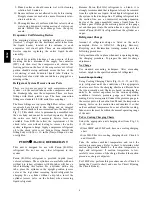
Page 10: ...10 COOLING CHARGING CHARTS C09221 Fig 10 Cooling Charging Charts 08D F Both Circuits 580J ...
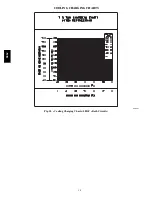
Page 11: ...11 COOLING CHARGING CHARTS C09222 Fig 11 Cooling Charging Charts 12D F Both Circuits 580J ...
Page 36: ...36 C07129 Fig 42 RTU MP Multi Protocol Control Board 580J ...
Page 37: ...37 C09163 Fig 43 Typical RTU MP System Control Wiring Diagram 580J ...
Page 60: ...60 C09156 Fig 73 580J Typical Unit Wiring Diagram Power 08D F 208 230 3 60 580J ...
Page 61: ...61 C09157 Fig 74 580J Typical Unit Wiring Diagram Control 08 12D F 208 230 3 60 580J ...
Page 84: ...84 580J ...


