


22
SD--TRK4 Remote Alarm Test Procedure
1. Turn the key switch to the RESET/TEST position for
seven seconds.
2. Verify that the test/reset station’s Alarm LED turns
on.
3. Reset the sensor by turning the key switch to the
RESET/TEST position for two seconds.
4. Verify that the test/reset station’s Alarm LED turns
off.
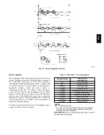
Remote Test/Reset Station Dirty Sensor Test
The test/reset station dirty sensor test checks the test/reset
station’s ability to initiate a sensor dirty test and indicate
the results. It must be wired to the controller as shown in
Fig. 27 and configured to operate the controller’s
supervision relay. For more information, see “Changing
the Dirty Sensor Test.”
1
12
14
13
19
15
2
20
3
Reset/Test
Trouble
Power
Alarm
Supervision relay
contacts [3]
5
4
1
3
2
SD-TRK4
2
1
TB3
18 Vdc ( )
+
18 Vdc ( )
−
Auxiliary
equipment
+
−
Wire must be
added by installer
Smoke Detector Controller
C08247
Fig. 27 -- Remote Test/Reset Station Connections
OPERATIONAL TEST HAZARD
Failure to follow this caution may result in personnel
and authority concern.
If the test/reset station’s key switch is left in the
RESET/TEST position for longer than seven seconds,
the detector will automatically go into the alarm state
and activate all automatic alarm responses.
CAUTION
!
OPERATIONAL TEST HAZARD
Failure to follow this caution may result in personnel
and authority concern.
Holding the test magnet to the target area for longer
than seven seconds will put the detector into the alarm
state and activate all automatic alarm responses.
CAUTION
!
Dirty Sensor Test Using an SD--TRK4
1. Turn the key switch to the RESET/TEST position for
two seconds.
2. Verify that the test/reset station’s Trouble LED
flashes.
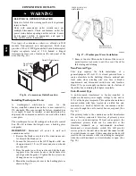
Detector Cleaning
Cleaning the Smoke Detector
Clean the duct smoke sensor when the Dirty LED is
flashing continuously or sooner if conditions warrant.
OPERATIONAL TEST HAZARD
Failure to follow this caution may result in personnel
and authority concern.
If the smoke detector is connected to a fire alarm
system, first notify the proper authorities that the
detector is undergoing maintenance then disable the
relevant circuit to avoid generating a false alarm.
CAUTION
!
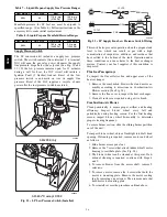
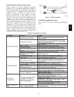
1. Disconnect power from the duct detector then remove
the sensor’s cover. (See Fig. 28.)
Airflow
HVAC duct
Sampling
tube
Retainer
clip
Optic
plate
Optic
housing
Sensor
housing
C07305
Fig. 28 -- Sensor Cleaning Diagram
2. Using a vacuum cleaner, clean compressed air, or a
soft bristle brush, remove loose dirt and debris from
inside the sensor housing and cover.
Use isopropyl alcohol and a lint--free cloth to remove
dirt and other contaminants from the gasket on the
sensor’s cover.
3. Squeeze the retainer clips on both sides of the optic
housing then lift the housing away from the printed
circuit board.
4. Gently remove dirt and debris from around the optic
plate and inside the optic housing.
5. Replace the optic housing and sensor cover.
6. Connect power to the duct detector then perform a
sensor alarm test.
580J
Summary of Contents for 580J*08--14D
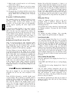
Page 10: ...10 COOLING CHARGING CHARTS C09221 Fig 10 Cooling Charging Charts 08D F Both Circuits 580J ...
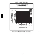
Page 11: ...11 COOLING CHARGING CHARTS C09222 Fig 11 Cooling Charging Charts 12D F Both Circuits 580J ...
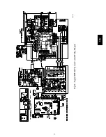
Page 36: ...36 C07129 Fig 42 RTU MP Multi Protocol Control Board 580J ...
Page 37: ...37 C09163 Fig 43 Typical RTU MP System Control Wiring Diagram 580J ...
Page 60: ...60 C09156 Fig 73 580J Typical Unit Wiring Diagram Power 08D F 208 230 3 60 580J ...
Page 61: ...61 C09157 Fig 74 580J Typical Unit Wiring Diagram Control 08 12D F 208 230 3 60 580J ...
Page 84: ...84 580J ...


