


286
GEARCASE
PROPELLER SERVICE
PROPELLER SERVICE
Inspection
Carefully examine propeller and outboard for the
following:
•
Damaged blades and signs of propeller cavita-
tion (burned paint, etc.)
•
Spun or overheated inner hub
•
Worn or twisted splines and inadequate lubri-
cant
•
Damaged or missing converging ring (if applica-
ble)
•
Damage to outer hub area
•
Worn, missing, or incorrect thrust washer and
spacer
•
Correct size and style
•
Check for bent or damaged propeller shaft and
twisted splines.
Refer to
Propeller Hardware Installation
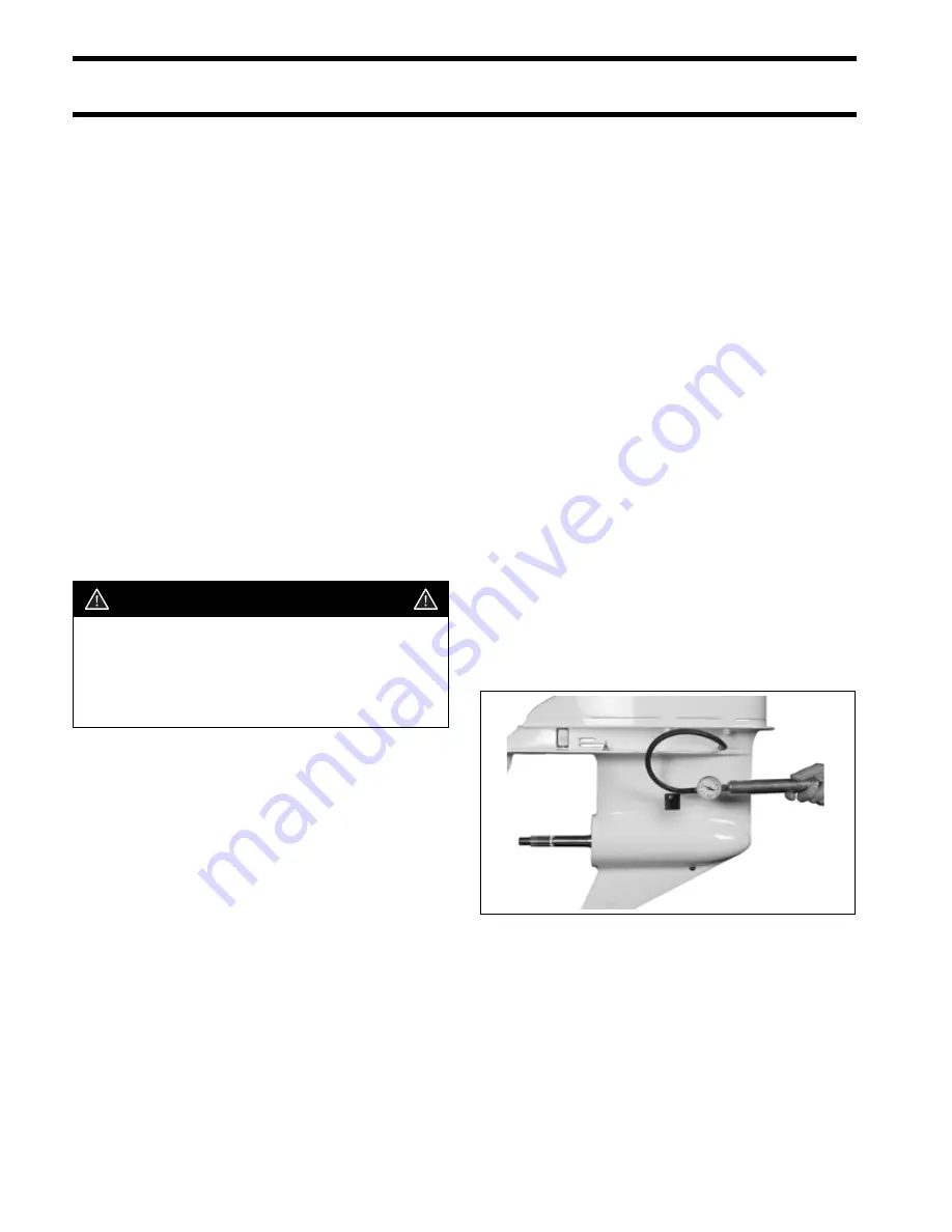
GEARCASE LEAK TEST
Drain lubricant before testing.
Install lubricant drain/fill plug and seal, thread
pressure test gauge fitting and seal in lubricant
level hole.
Pressurize 3 to 6 psi (21 to 42 kPa).
If pressure gauge indicates leakage, submerge
the gearcase in water to determine source of leak.
If the gearcase pressure gauge does not indicate
leakage, increase pressure to 16 to 18 psi (110 to
124 kPa). Check for leakage.
Make necessary repairs and repeat test.
Install vacuum test gauge. Apply 3 to 5 in. of vac-
uum (76 to 127 mm) Hg. with pump.
Check for leakage.
If leakage occurs, apply oil around suspected
seal. If leak then stops or oil is drawn in, that seal
is defective.
Repeat test. Gearcase must hold minimum of 15
in. (381 mm) Hg.
WARNING
When servicing the propeller, always shift
the outboard to NEUTRAL, turn the key
switch OFF, and disconnect the battery
positive (+) cable so the outboard cannot
be started accidentally.
002388
Summary of Contents for E200DHLSEB
Page 1: ...Main Menu...
Page 2: ......
Page 195: ...OILING SYSTEM OIL SUPPLY DIAGRAMS 193 9 3 3 L models 006870 Rear View 6 4 5 3 Top View 1 2...
Page 196: ...194 OILING SYSTEM OIL SUPPLY DIAGRAMS 3 4 L models 007256 Starboard View Port View...
Page 197: ...OILING SYSTEM OIL RECIRCULATION DIAGRAMS 195 9 OIL RECIRCULATION DIAGRAMS 004111a 2 4 6 1 3 5...
Page 248: ...246 POWERHEAD POWERHEAD VIEWS POWERHEAD VIEWS Port Hose Routings 3 3 L models 006951...
Page 249: ...POWERHEAD POWERHEAD VIEWS 247 11 Starboard Hose Routings 3 3 L models 006952...
Page 250: ...248 POWERHEAD POWERHEAD VIEWS Port Hose Routings 3 4 L models 007153...
Page 251: ...POWERHEAD POWERHEAD VIEWS 249 11 Starboard Hose Routings 3 4 L models 007154...
Page 252: ...250 POWERHEAD POWERHEAD VIEWS Port 3 3 L models 007139...
Page 253: ...POWERHEAD POWERHEAD VIEWS 251 11 Starboard 3 3 L models 007138...
Page 254: ...252 POWERHEAD POWERHEAD VIEWS Port 3 4 L models 007143...
Page 255: ...POWERHEAD POWERHEAD VIEWS 253 11 Starboard 3 4 L models 007144...
Page 256: ...254 POWERHEAD POWERHEAD VIEWS Front 3 3 L models 007140...
Page 257: ...POWERHEAD POWERHEAD VIEWS 255 11 Front 3 4 L models 007145...
Page 258: ...256 POWERHEAD POWERHEAD VIEWS Rear 3 3 L models 007141...
Page 259: ...POWERHEAD POWERHEAD VIEWS 257 11 Rear 3 4 L models 007142...
Page 260: ...258 POWERHEAD POWERHEAD VIEWS Top 007146...
Page 265: ...MIDSECTION SERVICE CHART 263 12 Muffler...
Page 364: ...S 2...
Page 396: ......
Page 405: ......
Page 412: ......


