


6-11
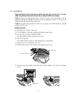
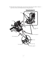
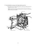
(24) Set the FFC stopper 2 to the carriage according to the following steps:
First, fit front and rear hooks "A" and "B" over section "a" and into hole "b," respectively Fit
cutout "C" and opening "D" over bosses "c" and "d," respectively. Then press the upper edge
of the FFC stopper 2 against the carriage so that latch "E" catches the carriage.
Close the FFC stopper 2.
(25) Set new ink cartridges into the print head unit.
(26) Close the scanner unit.
(27) While pressing the
Menu
key, plug the power cord into a wall socket.
The carriage automatically moves to the right-end home position.
(28) Press the
8
and
4
keys in this order to start a head cleaning cycle that will take approx. 5
minutes.
(29) Update the head property information stored in the EEPROM of the driver PCB, referring to
Appendix 2, A2.3.
(30) Load paper into the paper tray of the ASF.
(31) Press the
0
and
9
keys in this order to print out a test pattern. On the printed PRINT QUALITY
CHECK SHEET, check the color print quality according to the STEP A instructions. (Refer to
CHAPTER 7, Subsection 7.5.5.) If white horizontal streaks are found in any color block, press
the
8
and
4
keys as in step (28) and perform head cleaning for that color.
(32) Correct the positioning error of the print head unit, referring to Section 6.3 "ADJUSTMENT."
(33) If the print head unit is replaced with a new one, be sure to update the paper feeding correction
value stored in the EEPROM. Refer to Appendix A, A2.5 and CHAPTER 7, Subsection
7.5.14.
(34) Adjust the alignment of vertical print lines, referring to CHAPTER 7, Subsection 7.5.13.
Summary of Contents for MFC-5200C
Page 1: ...FACSIMILE EQUIPMENT SERVICE MANUAL MODEL MFC5200C MFC890 ...
Page 7: ...CHAPTER 1 PARTS NAMES FUNCTIONS ...
Page 8: ...CHAPTER 1 PARTS NAMES FUNCTIONS CONTENTS 1 1 EQUIPMENT OUTLINE 1 1 1 2 CONTROL PANEL 1 3 ...
Page 13: ...CHAPTER 2 SPECIFICATIONS ...
Page 18: ...2 4 2 1 4 Environmental Condition ...
Page 23: ...CHAPTER 3 INSTALLATION ...
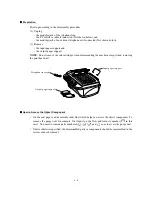
Page 26: ...3 2 3 2 UNPACKING THE MACHINE The equipment consists of the following major components ...
Page 34: ...CHAPTER 4 THEORY OF OPERATION ...
Page 54: ...CHAPTER 5 MAINTENANCE ...
Page 60: ...CHAPTER 6 DISASSEMBLY REASSEMBLY LUBRICATION AND ADJUSTMENT ...
Page 141: ...6 79 2 Separation roller and document feed roller 3 Document ejection roller ...
Page 146: ...6 84 11 Purge shaft EM4 Main chassis ...
Page 151: ...CHAPTER 7 MAINTENANCE MODE ...
Page 160: ...7 8 Scanning Compensation Data List ...
Page 174: ...7 22 Vertical Alignment Check Pattern ...
Page 183: ...CHAPTER 8 ERROR INDICATION AND TROUBLESHOOTING ...
Page 213: ...8 29 4 Close the manual feed cover ...
Page 214: ...MFC5200C MFC890 Appendix 1 Serial No Descriptions ...
Page 216: ... 2 PRINTER HEAD UNIT Location ...
Page 228: ...MFC5200C MFC890 Appendix 3 EEPROM Customizing Codes ...
Page 231: ...MFC5200C MFC890 Appendix 4 Firmware Switches WSW ...
Page 274: ...MFC5200C MFC890 Appendix 5 Re Packing Instructions ...
Page 276: ... 8 Place the machine in the original box with the original packaging material ...
Page 277: ...MFC5200C MFC890 Appendix 6 Wiring Diagram ...
Page 280: ...A Main PCB 1 4 MFC5200C ...
Page 281: ...A Main PCB 2 4 MFC5200C ...
Page 282: ...A Main PCB 3 4 MFC5200C ...
Page 283: ...A Main PCB 4 4 MFC5200C ...
Page 284: ...B Driver PCB 1 2 ...
Page 285: ...B Driver PCB 2 2 ...
Page 286: ...C NCU PCB MFC5200C ...
Page 287: ...D Control Panel PCB 1 2 MFC5200C ...
Page 288: ...D Control Panel PCB 1 2 MFC890 ...
Page 289: ...D Control Panel PCB 2 2 ...
Page 290: ...E Power Supply PCB MFC5200C ...
Page 291: ...F Carriage PCB ...
Page 292: ...G Media PCB 1 2 ...
Page 293: ...G Media PCB 2 2 ...


