


7-13
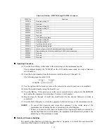
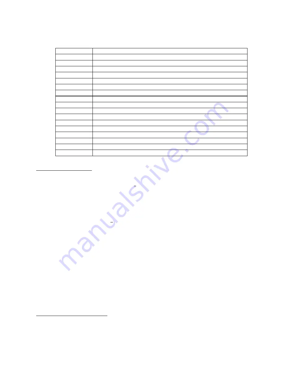
Firmware Switches (WSW01 through WSW50) Continued
WSW No.
Function
WSW34
Function setting 12
WSW35
Not used.
WSW36
Function setting 14
WSW37
Function setting 15
WSW38
Not used.
WSW39
Not used.
WSW40
Not used.
WSW41
CCD fluorescent lamp
WSW42
Function setting 20
WSW43
Function setting 21
WSW44
Speeding up scanning-1
WSW45
Speeding up scanning-2
WSW46
Monitor of power ON/OFF state and parallel port kept at high
WSW47
Paper handling for a feed error and delay of FAX line disconnection
WSW48
Not used.
WSW49
Not used.
WSW50
Not used.
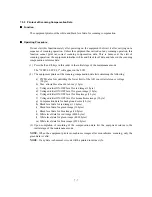
Operating Procedure
(1) Press the
1
and
0
keys in this order in the initial stage of the maintenance mode.
The equipment displays the "WSW00" on the LCD and becomes ready to accept a firmware
switch number.
(2) Enter the desired number from the firmware switch numbers (01 through 50).
The following appears on the LCD:
Selector 1
Selector 8
↓
↓
WSWXX = 0 0 0 0 0 0 0 0
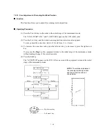
(3) Use the right and left arrow keys to move the cursor to the selector position to be modified.
(4) Enter the desired number using the
0
and
1
keys.
(5) Press the
Set
key. This operation saves the newly entered selector values onto the EEPROM
and readies the equipment for accepting a firmware switch number.
(6) Repeat steps (2) through (5) until the modification for the desired firmware switches is
completed.
(7) Press the
Set
or
Stop
key to return the equipment to the initial stage of the maintenance mode.
NOTES:
• To cancel this operation and return the equipment to the initial stage of the
maintenance mode during the above procedure, press the
Stop
key.
• If there is a pause of more than one minute after a single-digit number is entered for
double-digit firmware switch numbers, the equipment will automatically return to the
initial stage of the maintenance mode.
Details of Firmware Switches
The details of the firmware switches are described in Appendix 4 in which the user-accessible
selectors of the firmware switches are shaded.
Summary of Contents for MFC-5200C
Page 1: ...FACSIMILE EQUIPMENT SERVICE MANUAL MODEL MFC5200C MFC890 ...
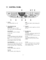
Page 7: ...CHAPTER 1 PARTS NAMES FUNCTIONS ...
Page 8: ...CHAPTER 1 PARTS NAMES FUNCTIONS CONTENTS 1 1 EQUIPMENT OUTLINE 1 1 1 2 CONTROL PANEL 1 3 ...
Page 13: ...CHAPTER 2 SPECIFICATIONS ...
Page 18: ...2 4 2 1 4 Environmental Condition ...
Page 23: ...CHAPTER 3 INSTALLATION ...
Page 26: ...3 2 3 2 UNPACKING THE MACHINE The equipment consists of the following major components ...
Page 34: ...CHAPTER 4 THEORY OF OPERATION ...
Page 54: ...CHAPTER 5 MAINTENANCE ...
Page 60: ...CHAPTER 6 DISASSEMBLY REASSEMBLY LUBRICATION AND ADJUSTMENT ...
Page 141: ...6 79 2 Separation roller and document feed roller 3 Document ejection roller ...
Page 146: ...6 84 11 Purge shaft EM4 Main chassis ...
Page 151: ...CHAPTER 7 MAINTENANCE MODE ...
Page 160: ...7 8 Scanning Compensation Data List ...
Page 174: ...7 22 Vertical Alignment Check Pattern ...
Page 183: ...CHAPTER 8 ERROR INDICATION AND TROUBLESHOOTING ...
Page 213: ...8 29 4 Close the manual feed cover ...
Page 214: ...MFC5200C MFC890 Appendix 1 Serial No Descriptions ...
Page 216: ... 2 PRINTER HEAD UNIT Location ...
Page 228: ...MFC5200C MFC890 Appendix 3 EEPROM Customizing Codes ...
Page 231: ...MFC5200C MFC890 Appendix 4 Firmware Switches WSW ...
Page 274: ...MFC5200C MFC890 Appendix 5 Re Packing Instructions ...
Page 276: ... 8 Place the machine in the original box with the original packaging material ...
Page 277: ...MFC5200C MFC890 Appendix 6 Wiring Diagram ...
Page 280: ...A Main PCB 1 4 MFC5200C ...
Page 281: ...A Main PCB 2 4 MFC5200C ...
Page 282: ...A Main PCB 3 4 MFC5200C ...
Page 283: ...A Main PCB 4 4 MFC5200C ...
Page 284: ...B Driver PCB 1 2 ...
Page 285: ...B Driver PCB 2 2 ...
Page 286: ...C NCU PCB MFC5200C ...
Page 287: ...D Control Panel PCB 1 2 MFC5200C ...
Page 288: ...D Control Panel PCB 1 2 MFC890 ...
Page 289: ...D Control Panel PCB 2 2 ...
Page 290: ...E Power Supply PCB MFC5200C ...
Page 291: ...F Carriage PCB ...
Page 292: ...G Media PCB 1 2 ...
Page 293: ...G Media PCB 2 2 ...


