


App. 4-29
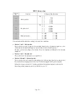
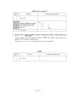
WSW28
(Function setting 6)
Selector
No.
Function
Setting and Specifications
1
|
3
Transmission level of DTMF
high-band frequency signal
No. 1 2 3
0 0 0
:
0 dB
0 0 1
:
+1 dB
0 1 0
:
+2 dB
0 1 1
:
+3 dB
1 0 0
:
0 dB
1 0 1
:
-1 dB
1 1 0
:
-2 dB
1 1 1
:
-3 dB
4
|
6
Transmission level of
DTMF low-band frequency
signal
No. 4 5 6
0 0 0
:
0 dB
0 0 1
:
+1 dB
0 1 0
:
+2 dB
0 1 1
:
+3 dB
1 0 0
:
0 dB
1 0 1
:
-1 dB
1 1 0
:
-2 dB
1 1 1
:
-3 dB
7
8
Not used.
Selectors 1 through 6: Transmission level of DTMF high-/low-band frequency signal
These selectors are intended for the manufacturer who tests the equipment for the Standard. Never
access them.
Summary of Contents for MFC-5200C
Page 1: ...FACSIMILE EQUIPMENT SERVICE MANUAL MODEL MFC5200C MFC890 ...
Page 7: ...CHAPTER 1 PARTS NAMES FUNCTIONS ...
Page 8: ...CHAPTER 1 PARTS NAMES FUNCTIONS CONTENTS 1 1 EQUIPMENT OUTLINE 1 1 1 2 CONTROL PANEL 1 3 ...
Page 13: ...CHAPTER 2 SPECIFICATIONS ...
Page 18: ...2 4 2 1 4 Environmental Condition ...
Page 23: ...CHAPTER 3 INSTALLATION ...
Page 26: ...3 2 3 2 UNPACKING THE MACHINE The equipment consists of the following major components ...
Page 34: ...CHAPTER 4 THEORY OF OPERATION ...
Page 54: ...CHAPTER 5 MAINTENANCE ...
Page 60: ...CHAPTER 6 DISASSEMBLY REASSEMBLY LUBRICATION AND ADJUSTMENT ...
Page 141: ...6 79 2 Separation roller and document feed roller 3 Document ejection roller ...
Page 146: ...6 84 11 Purge shaft EM4 Main chassis ...
Page 151: ...CHAPTER 7 MAINTENANCE MODE ...
Page 160: ...7 8 Scanning Compensation Data List ...
Page 174: ...7 22 Vertical Alignment Check Pattern ...
Page 183: ...CHAPTER 8 ERROR INDICATION AND TROUBLESHOOTING ...
Page 213: ...8 29 4 Close the manual feed cover ...
Page 214: ...MFC5200C MFC890 Appendix 1 Serial No Descriptions ...
Page 216: ... 2 PRINTER HEAD UNIT Location ...
Page 228: ...MFC5200C MFC890 Appendix 3 EEPROM Customizing Codes ...
Page 231: ...MFC5200C MFC890 Appendix 4 Firmware Switches WSW ...
Page 274: ...MFC5200C MFC890 Appendix 5 Re Packing Instructions ...
Page 276: ... 8 Place the machine in the original box with the original packaging material ...
Page 277: ...MFC5200C MFC890 Appendix 6 Wiring Diagram ...
Page 280: ...A Main PCB 1 4 MFC5200C ...
Page 281: ...A Main PCB 2 4 MFC5200C ...
Page 282: ...A Main PCB 3 4 MFC5200C ...
Page 283: ...A Main PCB 4 4 MFC5200C ...
Page 284: ...B Driver PCB 1 2 ...
Page 285: ...B Driver PCB 2 2 ...
Page 286: ...C NCU PCB MFC5200C ...
Page 287: ...D Control Panel PCB 1 2 MFC5200C ...
Page 288: ...D Control Panel PCB 1 2 MFC890 ...
Page 289: ...D Control Panel PCB 2 2 ...
Page 290: ...E Power Supply PCB MFC5200C ...
Page 291: ...F Carriage PCB ...
Page 292: ...G Media PCB 1 2 ...
Page 293: ...G Media PCB 2 2 ...


