


2-2
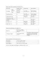
Paper capacity and specifications of the Paper Tray
Paper Type
Number of sheets
Paper Weight
Paper Thickness
Letter
Executive
100 of 20 lb
(80 g/m 2 )
Plain Paper
Legal
50 of 20 lb
(80 g/m 2 )
17 to 32 lb
(64 to 120 g/m 2 )
0.003 to 0.006 in.
(0.08 to 0.15 mm)
Inkjet Paper (Letter)
20
17 to 32 lb
(64 to 120 g/m 2 )
0.003 to 0.006 in.
(0.08 to 0.15 mm)
Glossy Paper (Letter)
20
Up to 40 lb
(150 g/m 2 )
Up to 0.007 in.
(0.18 mm)
Transparencies (Letter)
10
Envelopes (DL, COM-10, C5,
Monarch)
10
Up to 0.02 in.
(0.52mm)
Postcard 4" x 6"
30
Up to 45 lb
(170 g/m 2 )
Up to 0.009 in.
(0.23 mm)
Index Card 5" x 8"
30
Up to 32 lb
(120 g/m 2 )
Up to 0.006 in.
(0.15 mm)
Paper stack specifications for the Paper Tray
Paper tray
Up to 0.39 in. (10 mm)
Up to 100 sheets of 20 lb
(80 g/m 2 )
Output paper support
Up to 50 sheets of 20 lb
(80 g/m 2 )
(Transparencies and glossy paper must
be picked up from the output paper
support one page at a time to avoid
smudging.)
Paper specifications for the manual feed slot
Paper Width
3.5 to 8.5 in. (89 to 216 mm)
Paper Height
4 to 14 in. (102 to 356 mm)
Paper Thickness
0.005 to 0.01 in. (0.12 to 0.25 mm)
You have to remove paper from the paper tray and load one sheet at a time.
Summary of Contents for MFC-5200C
Page 1: ...FACSIMILE EQUIPMENT SERVICE MANUAL MODEL MFC5200C MFC890 ...
Page 7: ...CHAPTER 1 PARTS NAMES FUNCTIONS ...
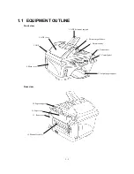
Page 8: ...CHAPTER 1 PARTS NAMES FUNCTIONS CONTENTS 1 1 EQUIPMENT OUTLINE 1 1 1 2 CONTROL PANEL 1 3 ...
Page 13: ...CHAPTER 2 SPECIFICATIONS ...
Page 18: ...2 4 2 1 4 Environmental Condition ...
Page 23: ...CHAPTER 3 INSTALLATION ...
Page 26: ...3 2 3 2 UNPACKING THE MACHINE The equipment consists of the following major components ...
Page 34: ...CHAPTER 4 THEORY OF OPERATION ...
Page 54: ...CHAPTER 5 MAINTENANCE ...
Page 60: ...CHAPTER 6 DISASSEMBLY REASSEMBLY LUBRICATION AND ADJUSTMENT ...
Page 141: ...6 79 2 Separation roller and document feed roller 3 Document ejection roller ...
Page 146: ...6 84 11 Purge shaft EM4 Main chassis ...
Page 151: ...CHAPTER 7 MAINTENANCE MODE ...
Page 160: ...7 8 Scanning Compensation Data List ...
Page 174: ...7 22 Vertical Alignment Check Pattern ...
Page 183: ...CHAPTER 8 ERROR INDICATION AND TROUBLESHOOTING ...
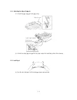
Page 213: ...8 29 4 Close the manual feed cover ...
Page 214: ...MFC5200C MFC890 Appendix 1 Serial No Descriptions ...
Page 216: ... 2 PRINTER HEAD UNIT Location ...
Page 228: ...MFC5200C MFC890 Appendix 3 EEPROM Customizing Codes ...
Page 231: ...MFC5200C MFC890 Appendix 4 Firmware Switches WSW ...
Page 274: ...MFC5200C MFC890 Appendix 5 Re Packing Instructions ...
Page 276: ... 8 Place the machine in the original box with the original packaging material ...
Page 277: ...MFC5200C MFC890 Appendix 6 Wiring Diagram ...
Page 280: ...A Main PCB 1 4 MFC5200C ...
Page 281: ...A Main PCB 2 4 MFC5200C ...
Page 282: ...A Main PCB 3 4 MFC5200C ...
Page 283: ...A Main PCB 4 4 MFC5200C ...
Page 284: ...B Driver PCB 1 2 ...
Page 285: ...B Driver PCB 2 2 ...
Page 286: ...C NCU PCB MFC5200C ...
Page 287: ...D Control Panel PCB 1 2 MFC5200C ...
Page 288: ...D Control Panel PCB 1 2 MFC890 ...
Page 289: ...D Control Panel PCB 2 2 ...
Page 290: ...E Power Supply PCB MFC5200C ...
Page 291: ...F Carriage PCB ...
Page 292: ...G Media PCB 1 2 ...
Page 293: ...G Media PCB 2 2 ...


