


7-21
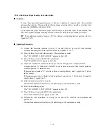
7.5.13 Alignment of Vertical Print Lines
Function
This function allows you to align vertical lines printed in the forward and backward direction of
the carriage.
NOTE:
Before this alignment job, be sure to correct the positioning error of the print head. (Refer
to CHAPTER 6, Section 6.3 "ADJUSTMENT.")
Operating Procedure
(1) Press the
6
and
5
keys in this order in the initial stage of the maintenance mode.
The equipment prints out a set of vertical alignment check patterns which consist of No. 1 to
No. 9 lines for each of the 600 dpi, 1200 dpi, and 450 dpi.
If the vertical alignment is ON, No. 5 line (each in the 600 dpi, 1200 dpi, and 450 dpi
printouts) shows vertically aligned lines as given on the next page.
The LCD shows the "600DPI NO.(1-9)."
(2) Check the printed vertical alignment check patterns for the 600 dpi and find which number
line shows full alignment. If the line is other than No. 5, enter that line number by using the
numerical keys.
The LCD shows the "1200DPI NO.(1-9)."
(3) For the 1200 dpi, perform the same operation as in step (2).
The LCD shows the "450DPI NO.(1-9)."
(4) For the 450 dpi, perform the same operation as in step (2).
The equipment automatically returns to the initial stage of the maintenance mode.
NOTE:
If No. 1 line or No. 9 line is fully aligned so that you press the
1
or
9
key in the above
procedure, then go back to step (1) to confirm that No. 5 line becomes aligned.
Summary of Contents for MFC-5200C
Page 1: ...FACSIMILE EQUIPMENT SERVICE MANUAL MODEL MFC5200C MFC890 ...
Page 7: ...CHAPTER 1 PARTS NAMES FUNCTIONS ...
Page 8: ...CHAPTER 1 PARTS NAMES FUNCTIONS CONTENTS 1 1 EQUIPMENT OUTLINE 1 1 1 2 CONTROL PANEL 1 3 ...
Page 13: ...CHAPTER 2 SPECIFICATIONS ...
Page 18: ...2 4 2 1 4 Environmental Condition ...
Page 23: ...CHAPTER 3 INSTALLATION ...
Page 26: ...3 2 3 2 UNPACKING THE MACHINE The equipment consists of the following major components ...
Page 34: ...CHAPTER 4 THEORY OF OPERATION ...
Page 54: ...CHAPTER 5 MAINTENANCE ...
Page 60: ...CHAPTER 6 DISASSEMBLY REASSEMBLY LUBRICATION AND ADJUSTMENT ...
Page 141: ...6 79 2 Separation roller and document feed roller 3 Document ejection roller ...
Page 146: ...6 84 11 Purge shaft EM4 Main chassis ...
Page 151: ...CHAPTER 7 MAINTENANCE MODE ...
Page 160: ...7 8 Scanning Compensation Data List ...
Page 174: ...7 22 Vertical Alignment Check Pattern ...
Page 183: ...CHAPTER 8 ERROR INDICATION AND TROUBLESHOOTING ...
Page 213: ...8 29 4 Close the manual feed cover ...
Page 214: ...MFC5200C MFC890 Appendix 1 Serial No Descriptions ...
Page 216: ... 2 PRINTER HEAD UNIT Location ...
Page 228: ...MFC5200C MFC890 Appendix 3 EEPROM Customizing Codes ...
Page 231: ...MFC5200C MFC890 Appendix 4 Firmware Switches WSW ...
Page 274: ...MFC5200C MFC890 Appendix 5 Re Packing Instructions ...
Page 276: ... 8 Place the machine in the original box with the original packaging material ...
Page 277: ...MFC5200C MFC890 Appendix 6 Wiring Diagram ...
Page 280: ...A Main PCB 1 4 MFC5200C ...
Page 281: ...A Main PCB 2 4 MFC5200C ...
Page 282: ...A Main PCB 3 4 MFC5200C ...
Page 283: ...A Main PCB 4 4 MFC5200C ...
Page 284: ...B Driver PCB 1 2 ...
Page 285: ...B Driver PCB 2 2 ...
Page 286: ...C NCU PCB MFC5200C ...
Page 287: ...D Control Panel PCB 1 2 MFC5200C ...
Page 288: ...D Control Panel PCB 1 2 MFC890 ...
Page 289: ...D Control Panel PCB 2 2 ...
Page 290: ...E Power Supply PCB MFC5200C ...
Page 291: ...F Carriage PCB ...
Page 292: ...G Media PCB 1 2 ...
Page 293: ...G Media PCB 2 2 ...


