


App. 4-2
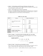
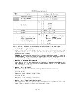
WSW01
(Dial pulse setting)
Selector
No.
Function
Setting and Specifications
1
2
Dial pulse generation mode
No. 1 2
0 0
:
N
0 1
:
N+1
1 0
:
10-N
1 1
:
N
3
4
Break time length in pulse dialing
No. 3 4
0 0
:
60 ms
0 1
:
67 ms
1 0
:
40 ms (for 16 PPS)
1 1
:
64 ms (at 106-ms intervals)
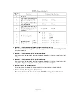
5
6
Inter-digit pause
No. 5 6
0 0
:
800 ms
0 1
:
850 ms
1 0
:
950 ms
1 1
:
600 ms
7
Switching between pulse (DP) and
tone (PB) dialing, by the function
switch
0: Yes
1:
No
8
Default dialing mode, pulse (DP)
or tone (PB) dialing
0: PB
1:
DP
Selectors 1 and 2: Dial pulse generation mode
These selectors set the number of pulses to be generated in pulse dialing.
N:
Dialing "N" generates "N" pulses. (Dialing "0" generates 10 pulses.)
N + 1: Dialing "N" generates "N + 1" pulses.
10 - N: Dialing "N" generates "10 - N" pulses.
Selectors 3 and 4: Break time length in pulse dialing
These selectors set the break time length in pulse dialing.
(Example: If "1," "2," and "3" are dialed when N is set by selectors 1 and 2.)
Selectors 5 and 6: Inter-digit pause
These selectors set the inter-digit pause in pulse dialing.
(Example: If "1," "2," and "3" are dialed when N is set by selectors 1 and 2.)
Summary of Contents for MFC-5200C
Page 1: ...FACSIMILE EQUIPMENT SERVICE MANUAL MODEL MFC5200C MFC890 ...
Page 7: ...CHAPTER 1 PARTS NAMES FUNCTIONS ...
Page 8: ...CHAPTER 1 PARTS NAMES FUNCTIONS CONTENTS 1 1 EQUIPMENT OUTLINE 1 1 1 2 CONTROL PANEL 1 3 ...
Page 13: ...CHAPTER 2 SPECIFICATIONS ...
Page 18: ...2 4 2 1 4 Environmental Condition ...
Page 23: ...CHAPTER 3 INSTALLATION ...
Page 26: ...3 2 3 2 UNPACKING THE MACHINE The equipment consists of the following major components ...
Page 34: ...CHAPTER 4 THEORY OF OPERATION ...
Page 54: ...CHAPTER 5 MAINTENANCE ...
Page 60: ...CHAPTER 6 DISASSEMBLY REASSEMBLY LUBRICATION AND ADJUSTMENT ...
Page 141: ...6 79 2 Separation roller and document feed roller 3 Document ejection roller ...
Page 146: ...6 84 11 Purge shaft EM4 Main chassis ...
Page 151: ...CHAPTER 7 MAINTENANCE MODE ...
Page 160: ...7 8 Scanning Compensation Data List ...
Page 174: ...7 22 Vertical Alignment Check Pattern ...
Page 183: ...CHAPTER 8 ERROR INDICATION AND TROUBLESHOOTING ...
Page 213: ...8 29 4 Close the manual feed cover ...
Page 214: ...MFC5200C MFC890 Appendix 1 Serial No Descriptions ...
Page 216: ... 2 PRINTER HEAD UNIT Location ...
Page 228: ...MFC5200C MFC890 Appendix 3 EEPROM Customizing Codes ...
Page 231: ...MFC5200C MFC890 Appendix 4 Firmware Switches WSW ...
Page 274: ...MFC5200C MFC890 Appendix 5 Re Packing Instructions ...
Page 276: ... 8 Place the machine in the original box with the original packaging material ...
Page 277: ...MFC5200C MFC890 Appendix 6 Wiring Diagram ...
Page 280: ...A Main PCB 1 4 MFC5200C ...
Page 281: ...A Main PCB 2 4 MFC5200C ...
Page 282: ...A Main PCB 3 4 MFC5200C ...
Page 283: ...A Main PCB 4 4 MFC5200C ...
Page 284: ...B Driver PCB 1 2 ...
Page 285: ...B Driver PCB 2 2 ...
Page 286: ...C NCU PCB MFC5200C ...
Page 287: ...D Control Panel PCB 1 2 MFC5200C ...
Page 288: ...D Control Panel PCB 1 2 MFC890 ...
Page 289: ...D Control Panel PCB 2 2 ...
Page 290: ...E Power Supply PCB MFC5200C ...
Page 291: ...F Carriage PCB ...
Page 292: ...G Media PCB 1 2 ...
Page 293: ...G Media PCB 2 2 ...


