


CHAPTER 7 MAINTENANCE MODE
CONTENTS
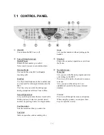
7.1
CONTROL PANEL...........................................................................................................7-1
7.2
ENTRY INTO THE MAINTENANCE MODE ....................................................................7-3
7.3
LIST OF MAINTENANCE-MODE FUNCTIONS ..............................................................7-4
7.4
USER-ACCESS TO THE MAINTENANCE MODE..........................................................7-5
7.5
DETAILED DESCRIPTION OF MAINTENANCE-MODE FUNCTIONS ..........................7-6
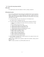
7.5.1
EEPROM Parameter Initialization ........................................................................7-6
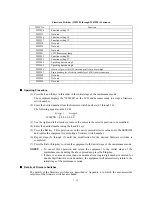
7.5.2
Printout of Scanning Compensation Data ............................................................7-7
7.5.3
Movement of CCD Unit to the Transport Position ................................................7-9
7.5.4
ADF Performance Test ......................................................................................7-10
7.5.5
Test Pattern 1.....................................................................................................7-11
7.5.6
Firmware Switch Setting and Printout ................................................................7-12
7.5.7
Operational Check of LCD .................................................................................7-15
7.5.8
Operational Check of Control Panel PCB ..........................................................7-16
7.5.9
Sensor Operational Check .................................................................................7-17
7.5.10 Fine Adjustment of Scanning Start/End Position ...............................................7-18
7.5.11 CCD Scanner Area Setting ................................................................................7-19
7.5.12 Setting the Sensing Reference Level of the Ink Empty Sensor .........................7-20
7.5.13 Alignment of Vertical Print Lines ........................................................................7-21
7.5.14 Updating of Paper Feeding Correction Value.....................................................7-23
7.5.15 Updating of Head Property Information..............................................................7-25
7.5.16 Initial Adjustment of PWM Value (Aging of the Carriage) ..................................7-26
7.5.17 EEPROM Customizing .......................................................................................7-27
7.5.18 Display of the Equipment's Log Information.......................................................7-28
7.5.19 Equipment Error Code Indication .......................................................................7-29
7.5.20 Output of Transmission Log to the Telephone Line ...........................................7-29
7.5.21 Cancellation of the Pin TX Lock Mode (Not applicable to American models)....7-30
Summary of Contents for MFC-5200C
Page 1: ...FACSIMILE EQUIPMENT SERVICE MANUAL MODEL MFC5200C MFC890 ...
Page 7: ...CHAPTER 1 PARTS NAMES FUNCTIONS ...
Page 8: ...CHAPTER 1 PARTS NAMES FUNCTIONS CONTENTS 1 1 EQUIPMENT OUTLINE 1 1 1 2 CONTROL PANEL 1 3 ...
Page 13: ...CHAPTER 2 SPECIFICATIONS ...
Page 18: ...2 4 2 1 4 Environmental Condition ...
Page 23: ...CHAPTER 3 INSTALLATION ...
Page 26: ...3 2 3 2 UNPACKING THE MACHINE The equipment consists of the following major components ...
Page 34: ...CHAPTER 4 THEORY OF OPERATION ...
Page 54: ...CHAPTER 5 MAINTENANCE ...
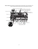
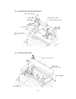
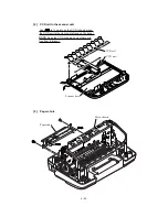
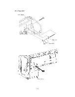
Page 60: ...CHAPTER 6 DISASSEMBLY REASSEMBLY LUBRICATION AND ADJUSTMENT ...
Page 141: ...6 79 2 Separation roller and document feed roller 3 Document ejection roller ...
Page 146: ...6 84 11 Purge shaft EM4 Main chassis ...
Page 151: ...CHAPTER 7 MAINTENANCE MODE ...
Page 160: ...7 8 Scanning Compensation Data List ...
Page 174: ...7 22 Vertical Alignment Check Pattern ...
Page 183: ...CHAPTER 8 ERROR INDICATION AND TROUBLESHOOTING ...
Page 213: ...8 29 4 Close the manual feed cover ...
Page 214: ...MFC5200C MFC890 Appendix 1 Serial No Descriptions ...
Page 216: ... 2 PRINTER HEAD UNIT Location ...
Page 228: ...MFC5200C MFC890 Appendix 3 EEPROM Customizing Codes ...
Page 231: ...MFC5200C MFC890 Appendix 4 Firmware Switches WSW ...
Page 274: ...MFC5200C MFC890 Appendix 5 Re Packing Instructions ...
Page 276: ... 8 Place the machine in the original box with the original packaging material ...
Page 277: ...MFC5200C MFC890 Appendix 6 Wiring Diagram ...
Page 280: ...A Main PCB 1 4 MFC5200C ...
Page 281: ...A Main PCB 2 4 MFC5200C ...
Page 282: ...A Main PCB 3 4 MFC5200C ...
Page 283: ...A Main PCB 4 4 MFC5200C ...
Page 284: ...B Driver PCB 1 2 ...
Page 285: ...B Driver PCB 2 2 ...
Page 286: ...C NCU PCB MFC5200C ...
Page 287: ...D Control Panel PCB 1 2 MFC5200C ...
Page 288: ...D Control Panel PCB 1 2 MFC890 ...
Page 289: ...D Control Panel PCB 2 2 ...
Page 290: ...E Power Supply PCB MFC5200C ...
Page 291: ...F Carriage PCB ...
Page 292: ...G Media PCB 1 2 ...
Page 293: ...G Media PCB 2 2 ...


