


8-22
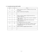
Trouble
Action to be taken
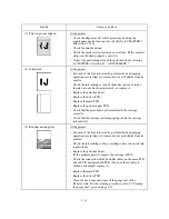
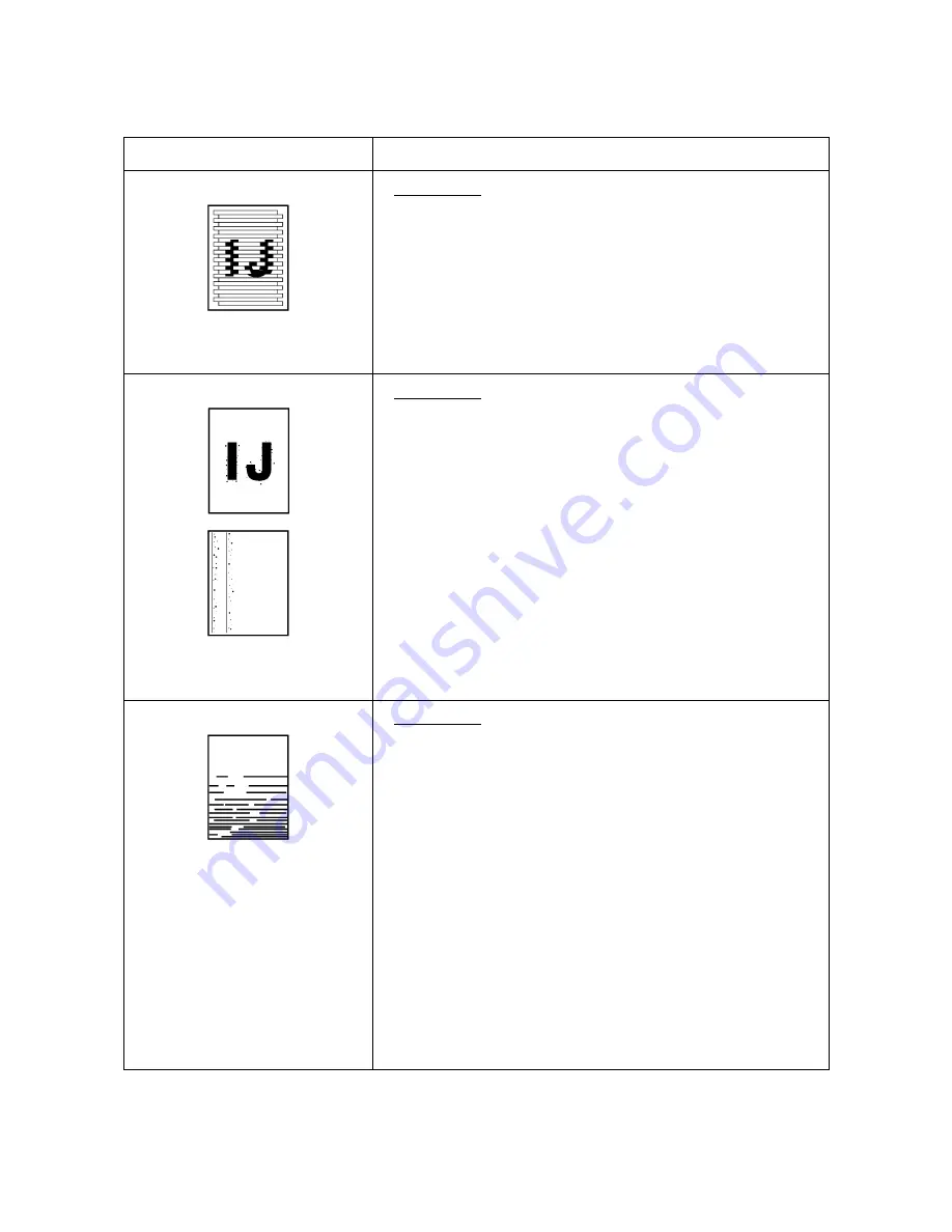
(7)
Print edges not aligned
At the printer
• Check the alignment of vertical print lines by using the
maintenance-mode function code 65. (Refer to CHAPTER 7,
Subsection 7.5.13).
• Check the print head unit.
• Check the encoder strip for stains or scratches. (If the encoder
strip is not hooked properly, correct it.)
• Correct the positioning error of the print head unit, referring
to CHAPTER 6, Section 6.3, "ADJUSTMENT."
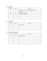
(8)
Ink splash
At the printer
• For each of the four ink-jet units, perform the head purging
operation several times to remove dust or air bubbles from its
nozzles.
• Check the ink cartridges. Any of them has run out of ink or
the ink viscosity has been increased, so replace it.
• Replace the print head unit.
• Replace the driver PCB.
• Replace the main PCB.
• Replace the power supply PCB.
• Check that the print head unit is installed to the carriage
correctly.
• Check that the carriage rail clamp springs catch the carriage
rail correctly.
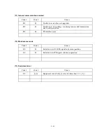
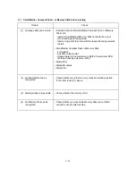
(9)
Random missing dots
At the printer
• For each of the four ink-jet units, perform the head purging
operation several times to remove dust or air bubbles from its
nozzles.
• Check the ink cartridges. If any cartridges have run out of ink,
replace them.
• Replace the print head unit.
(If the problem persists, replace the carriage ASSY.)
• Check the connection of the head flat cables on the main PCB,
driver PCB, and print head PCB. (If any of those cables is
broken or damaged, replace it.)
• Replace the main PCB.
• Replace the driver PCB.
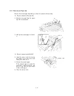
• Clean the head caps and wiper of the purge unit with a
Rubycel stick. For the cleaning procedure, refer to "Cleaning
the purge unit" given on page 8-25.
Summary of Contents for MFC-5200C
Page 1: ...FACSIMILE EQUIPMENT SERVICE MANUAL MODEL MFC5200C MFC890 ...
Page 7: ...CHAPTER 1 PARTS NAMES FUNCTIONS ...
Page 8: ...CHAPTER 1 PARTS NAMES FUNCTIONS CONTENTS 1 1 EQUIPMENT OUTLINE 1 1 1 2 CONTROL PANEL 1 3 ...
Page 13: ...CHAPTER 2 SPECIFICATIONS ...
Page 18: ...2 4 2 1 4 Environmental Condition ...
Page 23: ...CHAPTER 3 INSTALLATION ...
Page 26: ...3 2 3 2 UNPACKING THE MACHINE The equipment consists of the following major components ...
Page 34: ...CHAPTER 4 THEORY OF OPERATION ...
Page 54: ...CHAPTER 5 MAINTENANCE ...
Page 60: ...CHAPTER 6 DISASSEMBLY REASSEMBLY LUBRICATION AND ADJUSTMENT ...
Page 141: ...6 79 2 Separation roller and document feed roller 3 Document ejection roller ...
Page 146: ...6 84 11 Purge shaft EM4 Main chassis ...
Page 151: ...CHAPTER 7 MAINTENANCE MODE ...
Page 160: ...7 8 Scanning Compensation Data List ...
Page 174: ...7 22 Vertical Alignment Check Pattern ...
Page 183: ...CHAPTER 8 ERROR INDICATION AND TROUBLESHOOTING ...
Page 213: ...8 29 4 Close the manual feed cover ...
Page 214: ...MFC5200C MFC890 Appendix 1 Serial No Descriptions ...
Page 216: ... 2 PRINTER HEAD UNIT Location ...
Page 228: ...MFC5200C MFC890 Appendix 3 EEPROM Customizing Codes ...
Page 231: ...MFC5200C MFC890 Appendix 4 Firmware Switches WSW ...
Page 274: ...MFC5200C MFC890 Appendix 5 Re Packing Instructions ...
Page 276: ... 8 Place the machine in the original box with the original packaging material ...
Page 277: ...MFC5200C MFC890 Appendix 6 Wiring Diagram ...
Page 280: ...A Main PCB 1 4 MFC5200C ...
Page 281: ...A Main PCB 2 4 MFC5200C ...
Page 282: ...A Main PCB 3 4 MFC5200C ...
Page 283: ...A Main PCB 4 4 MFC5200C ...
Page 284: ...B Driver PCB 1 2 ...
Page 285: ...B Driver PCB 2 2 ...
Page 286: ...C NCU PCB MFC5200C ...
Page 287: ...D Control Panel PCB 1 2 MFC5200C ...
Page 288: ...D Control Panel PCB 1 2 MFC890 ...
Page 289: ...D Control Panel PCB 2 2 ...
Page 290: ...E Power Supply PCB MFC5200C ...
Page 291: ...F Carriage PCB ...
Page 292: ...G Media PCB 1 2 ...
Page 293: ...G Media PCB 2 2 ...


