


7-20
7.5.12 Setting the Sensing Reference Level of the Ink Empty Sensor
Function
This function allows you to set the sensing reference level of the ink empty sensor which apply
when the controller judges whether there is ink in the ink cartridges. The setting procedure
requires a foam-empty cartridge as a reference cartridge.
NOTE:
If you replace the driver PCB or ink empty sensor, carry out this procedure.
Operating Procedure
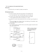
Handling notes for the reference cartridge:
Shown below is a foam-empty cartridge to be used
for setting the sensing reference level of the ink empty sensor. Do not touch section "x" or "y."
If any dust or dirt is found on "x" or "y," wipe it off with a soft cloth. If "x" is scratched, replace
the cartridge with a new one. Using such a scratched cartridge will fail to set correct reference
level. After completion of the setting procedure, store the cartridge in the container.
Foam-empty cartridge
(1) Press the
5
and
7
keys in this order in the initial stage of the maintenance mode.
(2) Open the scanner unit.
The carriage automatically moves left to the ink replacement position.
(3) Remove the yellow ink cartridge.
The LCD shows "SET F.EMP CART!!."
NOTE:
When this message is displayed, do not load or unload any other ink cartridges.
(4) Set the foam-empty cartridge into the yellow ink cartridge position.
The LCD shows "CLOSE COVER!!."
(5) Close the scanner unit.
The equipment shows the "-INKEMP CHECK-" and starts setting the sensing level for the
foam-empty cartridge.
If the equipment completes setting normally, it beeps and displays the "INKEMP TST:OK!."
If it fails, the "INKEMP F.EMP:NG!" appears, so press the
Stop
key and go back to step (1).
(6) Open the scanner unit and remove the foam-empty cartridge.
(7) Load the yellow ink cartridge removed in step (3) back into place.
(8) Press the
Stop
key to return to the initial stage of the maintenance mode.
Summary of Contents for MFC-5200C
Page 1: ...FACSIMILE EQUIPMENT SERVICE MANUAL MODEL MFC5200C MFC890 ...
Page 7: ...CHAPTER 1 PARTS NAMES FUNCTIONS ...
Page 8: ...CHAPTER 1 PARTS NAMES FUNCTIONS CONTENTS 1 1 EQUIPMENT OUTLINE 1 1 1 2 CONTROL PANEL 1 3 ...
Page 13: ...CHAPTER 2 SPECIFICATIONS ...
Page 18: ...2 4 2 1 4 Environmental Condition ...
Page 23: ...CHAPTER 3 INSTALLATION ...
Page 26: ...3 2 3 2 UNPACKING THE MACHINE The equipment consists of the following major components ...
Page 34: ...CHAPTER 4 THEORY OF OPERATION ...
Page 54: ...CHAPTER 5 MAINTENANCE ...
Page 60: ...CHAPTER 6 DISASSEMBLY REASSEMBLY LUBRICATION AND ADJUSTMENT ...
Page 141: ...6 79 2 Separation roller and document feed roller 3 Document ejection roller ...
Page 146: ...6 84 11 Purge shaft EM4 Main chassis ...
Page 151: ...CHAPTER 7 MAINTENANCE MODE ...
Page 160: ...7 8 Scanning Compensation Data List ...
Page 174: ...7 22 Vertical Alignment Check Pattern ...
Page 183: ...CHAPTER 8 ERROR INDICATION AND TROUBLESHOOTING ...
Page 213: ...8 29 4 Close the manual feed cover ...
Page 214: ...MFC5200C MFC890 Appendix 1 Serial No Descriptions ...
Page 216: ... 2 PRINTER HEAD UNIT Location ...
Page 228: ...MFC5200C MFC890 Appendix 3 EEPROM Customizing Codes ...
Page 231: ...MFC5200C MFC890 Appendix 4 Firmware Switches WSW ...
Page 274: ...MFC5200C MFC890 Appendix 5 Re Packing Instructions ...
Page 276: ... 8 Place the machine in the original box with the original packaging material ...
Page 277: ...MFC5200C MFC890 Appendix 6 Wiring Diagram ...
Page 280: ...A Main PCB 1 4 MFC5200C ...
Page 281: ...A Main PCB 2 4 MFC5200C ...
Page 282: ...A Main PCB 3 4 MFC5200C ...
Page 283: ...A Main PCB 4 4 MFC5200C ...
Page 284: ...B Driver PCB 1 2 ...
Page 285: ...B Driver PCB 2 2 ...
Page 286: ...C NCU PCB MFC5200C ...
Page 287: ...D Control Panel PCB 1 2 MFC5200C ...
Page 288: ...D Control Panel PCB 1 2 MFC890 ...
Page 289: ...D Control Panel PCB 2 2 ...
Page 290: ...E Power Supply PCB MFC5200C ...
Page 291: ...F Carriage PCB ...
Page 292: ...G Media PCB 1 2 ...
Page 293: ...G Media PCB 2 2 ...


