


7-17
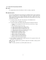
7.5.9 Sensor Operational Check
Function
This function allows you to check the following:
- Document front sensor
- Document rear sensor
- Document cover open sensor
- CCD HP sensor
- Scanner open sensor
- Registration sensor
- Paper width sensor
- Purge cam HP switch
- Pump switching cam HP switch
- (Print head detector)
- Black ink cartridge sensor
- Yellow ink cartridge sensor
- Cyan ink cartridge sensor
- Magenta ink cartridge sensor
- Manual feed slot cover sensor
Operating Procedure
(1) Press the
3
and
2
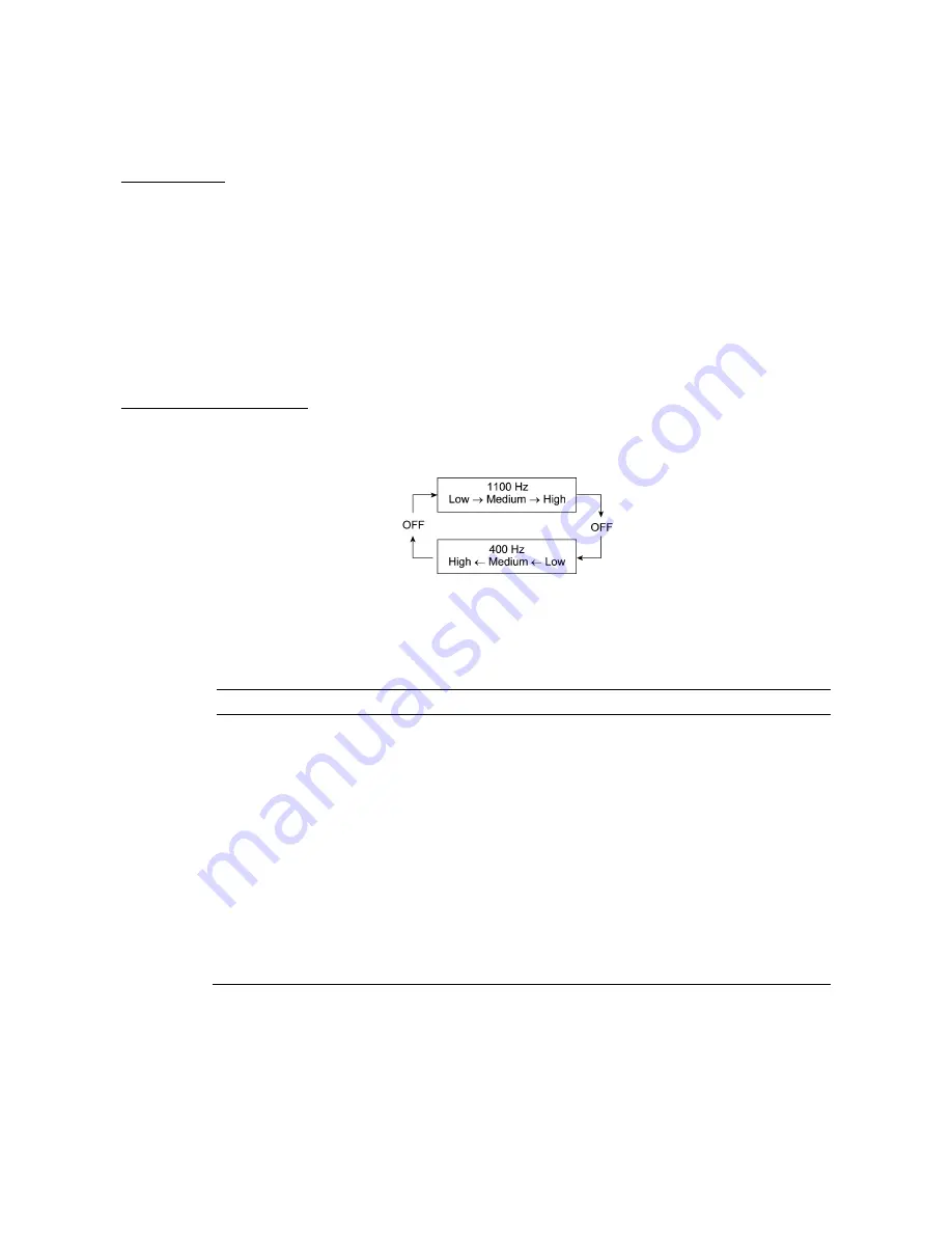
keys in this order in the initial stage of the maintenance mode. The
equipment sounds 1100 Hz and 400 Hz tones cyclically through the following volumes for
testing the speaker:
NOTE:
To stop beeping, press the
Menu
key.
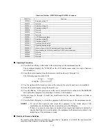
If the sensing status are as listed below, the LCD will show "DFDRDCFHCSCVRSPW" and
"P1P2HDIKIYICIMMP," which can be switched by pressing the
Fax Start
key.
Given below is the relationship between the LCD indication, sensor name and sensor status.
LCD
Sensors
Sensing status
DF
Document front sensor
No document detected.
DR
Document rear sensor
No document detected.
DC
Document cover open sensor
Document cover closed.
FH
CCD HP sensor
CCD unit placed in the home position.
CS
Cassette sensor
Not applicable to the MFC5200C/MFC890
CV
Scanner open sensor
Scanner unit closed.
RS
Registration sensor
No recording paper detected.
PW
Paper width sensor
No paper detected.
P1
Purge cam HP switch
Purge cam placed in the home position.
P2
Pump switching cam HP switch
Pump switching cam placed in the home position.
HD
(Print head detector)
(Not used.)
IK
Black ink cartridge sensor
Black ink cartridge loaded.
IY
Yellow ink cartridge sensor
Yellow ink cartridge loaded.
IC
Cyan ink cartridge sensor
Cyan ink cartridge loaded.
IM
Magenta ink cartridge sensor
Magenta ink cartridge loaded.
MP
Manual feed slot cover sensor
Manual feed slot cover closed.
(2) Change the detecting conditions (e.g., insert paper through the document sensors, registration
sensor or paper width sensor, open the document cover/scanner unit/manual feed slot cover, or
remove the print head or ink cartridges) and then check that the indication on the LCD
changes according to the sensor states.
(3) To stop this operation and return the equipment to the initial stage of the maintenance mode,
press the
Stop
key.
Summary of Contents for MFC-5200C
Page 1: ...FACSIMILE EQUIPMENT SERVICE MANUAL MODEL MFC5200C MFC890 ...
Page 7: ...CHAPTER 1 PARTS NAMES FUNCTIONS ...
Page 8: ...CHAPTER 1 PARTS NAMES FUNCTIONS CONTENTS 1 1 EQUIPMENT OUTLINE 1 1 1 2 CONTROL PANEL 1 3 ...
Page 13: ...CHAPTER 2 SPECIFICATIONS ...
Page 18: ...2 4 2 1 4 Environmental Condition ...
Page 23: ...CHAPTER 3 INSTALLATION ...
Page 26: ...3 2 3 2 UNPACKING THE MACHINE The equipment consists of the following major components ...
Page 34: ...CHAPTER 4 THEORY OF OPERATION ...
Page 54: ...CHAPTER 5 MAINTENANCE ...
Page 60: ...CHAPTER 6 DISASSEMBLY REASSEMBLY LUBRICATION AND ADJUSTMENT ...
Page 141: ...6 79 2 Separation roller and document feed roller 3 Document ejection roller ...
Page 146: ...6 84 11 Purge shaft EM4 Main chassis ...
Page 151: ...CHAPTER 7 MAINTENANCE MODE ...
Page 160: ...7 8 Scanning Compensation Data List ...
Page 174: ...7 22 Vertical Alignment Check Pattern ...
Page 183: ...CHAPTER 8 ERROR INDICATION AND TROUBLESHOOTING ...
Page 213: ...8 29 4 Close the manual feed cover ...
Page 214: ...MFC5200C MFC890 Appendix 1 Serial No Descriptions ...
Page 216: ... 2 PRINTER HEAD UNIT Location ...
Page 228: ...MFC5200C MFC890 Appendix 3 EEPROM Customizing Codes ...
Page 231: ...MFC5200C MFC890 Appendix 4 Firmware Switches WSW ...
Page 274: ...MFC5200C MFC890 Appendix 5 Re Packing Instructions ...
Page 276: ... 8 Place the machine in the original box with the original packaging material ...
Page 277: ...MFC5200C MFC890 Appendix 6 Wiring Diagram ...
Page 280: ...A Main PCB 1 4 MFC5200C ...
Page 281: ...A Main PCB 2 4 MFC5200C ...
Page 282: ...A Main PCB 3 4 MFC5200C ...
Page 283: ...A Main PCB 4 4 MFC5200C ...
Page 284: ...B Driver PCB 1 2 ...
Page 285: ...B Driver PCB 2 2 ...
Page 286: ...C NCU PCB MFC5200C ...
Page 287: ...D Control Panel PCB 1 2 MFC5200C ...
Page 288: ...D Control Panel PCB 1 2 MFC890 ...
Page 289: ...D Control Panel PCB 2 2 ...
Page 290: ...E Power Supply PCB MFC5200C ...
Page 291: ...F Carriage PCB ...
Page 292: ...G Media PCB 1 2 ...
Page 293: ...G Media PCB 2 2 ...


