


4-18
4.3 CONTROL ELECTRONICS
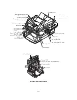
4.3.1 Configuration
The hardware configuration of the facsimile machine is shown below. The wiring diagram is given
in Appendix 6.
Power supply PCB
Compact Flash
SmartMedia
Memory Stick
Media PCB
22-pin
21-pin
USB
Parallel I/F
NCU PCB
Main PCB
7-pin
(10-pin)*
PC
Line
External telephone
Control panel PCB
ASSY
(Scanner open
sensor)
SCANNER UNIT
CCD unit
(CCD motor)
(CCD HP sensor)
Speaker
2-pin
60-pin
2-pin
Manual feed
slot cover sensor
EEPROM
LAN (option)
MODEM
ROM
4/8 MB
SDRAM
8MB
ASIC
SUB GA
Main-
driver
connector
Document cover
open sensor
ADF UNIT
Document sensor PCB
(Document front sensor
and document rear sensor)
ADF motor
10-pin 7-pin
Registration sensor
Paper width sensor
Driver PCB
3-pin
DC motor driver
Stepping motor driver
2-pin
4-pin
4-pin
Print head PCB
Print head
Print head
Print head
Print head
INK JET PRINTER UNIT
Carriage PCB
Ink cartridge sensors
Carriage encoder
Head thermister
Ink empty sensor PCB
Carriage motor
Paper feed motor
Purge unit
Sensor support
Purge cam HP switch
Pump switching cam HP switch
13-pin
* 7-pin: American models
10-pin: Other models
AC line
Configuration of Facsimile Machine
Summary of Contents for MFC-5200C
Page 1: ...FACSIMILE EQUIPMENT SERVICE MANUAL MODEL MFC5200C MFC890 ...
Page 7: ...CHAPTER 1 PARTS NAMES FUNCTIONS ...
Page 8: ...CHAPTER 1 PARTS NAMES FUNCTIONS CONTENTS 1 1 EQUIPMENT OUTLINE 1 1 1 2 CONTROL PANEL 1 3 ...
Page 13: ...CHAPTER 2 SPECIFICATIONS ...
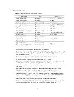
Page 18: ...2 4 2 1 4 Environmental Condition ...
Page 23: ...CHAPTER 3 INSTALLATION ...
Page 26: ...3 2 3 2 UNPACKING THE MACHINE The equipment consists of the following major components ...
Page 34: ...CHAPTER 4 THEORY OF OPERATION ...
Page 54: ...CHAPTER 5 MAINTENANCE ...
Page 60: ...CHAPTER 6 DISASSEMBLY REASSEMBLY LUBRICATION AND ADJUSTMENT ...
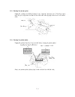
Page 141: ...6 79 2 Separation roller and document feed roller 3 Document ejection roller ...
Page 146: ...6 84 11 Purge shaft EM4 Main chassis ...
Page 151: ...CHAPTER 7 MAINTENANCE MODE ...
Page 160: ...7 8 Scanning Compensation Data List ...
Page 174: ...7 22 Vertical Alignment Check Pattern ...
Page 183: ...CHAPTER 8 ERROR INDICATION AND TROUBLESHOOTING ...
Page 213: ...8 29 4 Close the manual feed cover ...
Page 214: ...MFC5200C MFC890 Appendix 1 Serial No Descriptions ...
Page 216: ... 2 PRINTER HEAD UNIT Location ...
Page 228: ...MFC5200C MFC890 Appendix 3 EEPROM Customizing Codes ...
Page 231: ...MFC5200C MFC890 Appendix 4 Firmware Switches WSW ...
Page 274: ...MFC5200C MFC890 Appendix 5 Re Packing Instructions ...
Page 276: ... 8 Place the machine in the original box with the original packaging material ...
Page 277: ...MFC5200C MFC890 Appendix 6 Wiring Diagram ...
Page 280: ...A Main PCB 1 4 MFC5200C ...
Page 281: ...A Main PCB 2 4 MFC5200C ...
Page 282: ...A Main PCB 3 4 MFC5200C ...
Page 283: ...A Main PCB 4 4 MFC5200C ...
Page 284: ...B Driver PCB 1 2 ...
Page 285: ...B Driver PCB 2 2 ...
Page 286: ...C NCU PCB MFC5200C ...
Page 287: ...D Control Panel PCB 1 2 MFC5200C ...
Page 288: ...D Control Panel PCB 1 2 MFC890 ...
Page 289: ...D Control Panel PCB 2 2 ...
Page 290: ...E Power Supply PCB MFC5200C ...
Page 291: ...F Carriage PCB ...
Page 292: ...G Media PCB 1 2 ...
Page 293: ...G Media PCB 2 2 ...


