


6-52
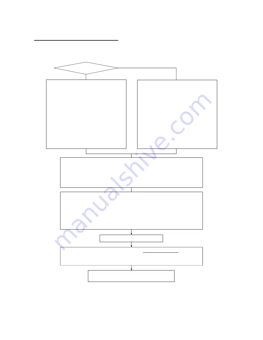
Setting up the driver PCB after replacement
- - - - - - - - - - - - - - - - - - - - - - - - - - - - - - - - - - - - - -
Important
- - - - - - - - - - - - - - - - - - - - - - - - - - - - - - - - - - - -
NOTE:
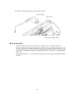
Before starting the following procedure, make sure that the print head unit is installed.
Replaced with a
new driver PCB?
Make the machine exit from the maintenance mode by pressing the
9
key twice.
(Refer to CHAPTER 7.) If you turn the machine off without pressing the
9
key twice, the next
powering-on will restore the machine to the maintenance mode where purging operation will
automatically take place.
N
Y
Turn the machine off and on.
When the machine is carrying out the purging operation and aging of the carriage,
press the
Stop
key to return to the initial stage of the maintenance mode.
Then perform the following:
- Sensor operational check
[Function code: 32]
- Operational check of control panel PCB
[Function code: 13]
After completion of the purging operation and aging of the carriage, perform the following:
- ADF performance test
[Function code: 08]
- Updating of paper feeding correction value
[Function code: 66]
- Alignment of vertical print lines
[Function code: 65]
- Operational check of LCD
[Function code: 12]
Set an ID code and head property data to the machine.
(Refer to Appendix 2, A2.2 and A2.3.)
The machine automatically enters the maintenance
mode.
Then perform the following:
- EEPROM customizing
[Function code: 74]
- CCD scanner area setting
[Function code: 55]
- Setting the sensing reference level of the ink
empty sensor [Function code: 57]
(Refer to CHAPTER 7.)
Following the sensitivity level setting, the machine
automatically carries out the purging operation and
aging of the carriage. (This will take approx.
7 minutes.)
Make the machine enter the maintenance mode
and then perform the following:
- EEPROM parameter initialization
[Function code: 01]
- EEPROM customizing
[Function code: 74]
- CCD scanner area setting
[Function code: 55]
- Setting the sensing reference level of the ink
empty sensor [Function code: 57]
(Refer to CHAPTER 7.)
Following the sensitivity level setting, the machine
automatically carries out the purging operation and
aging of the carriage. (This will take approx.
7 minutes.)
Summary of Contents for MFC-5200C
Page 1: ...FACSIMILE EQUIPMENT SERVICE MANUAL MODEL MFC5200C MFC890 ...
Page 7: ...CHAPTER 1 PARTS NAMES FUNCTIONS ...
Page 8: ...CHAPTER 1 PARTS NAMES FUNCTIONS CONTENTS 1 1 EQUIPMENT OUTLINE 1 1 1 2 CONTROL PANEL 1 3 ...
Page 13: ...CHAPTER 2 SPECIFICATIONS ...
Page 18: ...2 4 2 1 4 Environmental Condition ...
Page 23: ...CHAPTER 3 INSTALLATION ...
Page 26: ...3 2 3 2 UNPACKING THE MACHINE The equipment consists of the following major components ...
Page 34: ...CHAPTER 4 THEORY OF OPERATION ...
Page 54: ...CHAPTER 5 MAINTENANCE ...
Page 60: ...CHAPTER 6 DISASSEMBLY REASSEMBLY LUBRICATION AND ADJUSTMENT ...
Page 141: ...6 79 2 Separation roller and document feed roller 3 Document ejection roller ...
Page 146: ...6 84 11 Purge shaft EM4 Main chassis ...
Page 151: ...CHAPTER 7 MAINTENANCE MODE ...
Page 160: ...7 8 Scanning Compensation Data List ...
Page 174: ...7 22 Vertical Alignment Check Pattern ...
Page 183: ...CHAPTER 8 ERROR INDICATION AND TROUBLESHOOTING ...
Page 213: ...8 29 4 Close the manual feed cover ...
Page 214: ...MFC5200C MFC890 Appendix 1 Serial No Descriptions ...
Page 216: ... 2 PRINTER HEAD UNIT Location ...
Page 228: ...MFC5200C MFC890 Appendix 3 EEPROM Customizing Codes ...
Page 231: ...MFC5200C MFC890 Appendix 4 Firmware Switches WSW ...
Page 274: ...MFC5200C MFC890 Appendix 5 Re Packing Instructions ...
Page 276: ... 8 Place the machine in the original box with the original packaging material ...
Page 277: ...MFC5200C MFC890 Appendix 6 Wiring Diagram ...
Page 280: ...A Main PCB 1 4 MFC5200C ...
Page 281: ...A Main PCB 2 4 MFC5200C ...
Page 282: ...A Main PCB 3 4 MFC5200C ...
Page 283: ...A Main PCB 4 4 MFC5200C ...
Page 284: ...B Driver PCB 1 2 ...
Page 285: ...B Driver PCB 2 2 ...
Page 286: ...C NCU PCB MFC5200C ...
Page 287: ...D Control Panel PCB 1 2 MFC5200C ...
Page 288: ...D Control Panel PCB 1 2 MFC890 ...
Page 289: ...D Control Panel PCB 2 2 ...
Page 290: ...E Power Supply PCB MFC5200C ...
Page 291: ...F Carriage PCB ...
Page 292: ...G Media PCB 1 2 ...
Page 293: ...G Media PCB 2 2 ...


