


7-28
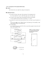
7.5.18 Display of the Equipment's Log Information
Function
The equipment may display the its log information on the LCD.
Operating Procedure
(1) Press the
8
and
0
keys in this order in the initial stage of the maintenance mode.
The USB serial number appears on the LCD.
(2) Press the
Fax
Start
key. Each time the
Fax
Start
key is pressed, one of the following log
information items appears on the LCD in the order given below.
1) Ink cartridge drop count, indicating how many droplets have been jetted out from each of
the ink cartridges*
1
2) Ink drop count after near-empty, indicating how many droplets have been jetted out from
each of the ink cartridges*
1
after the ink empty sensor detects near-empty
3) Total ink drop count, indicating how many droplets the equipment has been jetted out
from each of the ink cartridges*
1
since produced
4) Jam count, indicating how many times a paper jam has been occurred
5) Total page count, indicating how many pages have been printed since the equipment was
produced
6) PC print page count, indicating how many pages the equipment has been printed as an
output device of the connected PC
7) Copy page count, indicating how many copies have been made
8) FAX page count, indicating how many received FAX pages have been printed
9) Purge count, indicating how many times the purge operation has been carried out
10) Wiper count, indicating how many times the wiper operation has been carried out
11) Ink cartridge change count, indicating how many times ink cartridge replacement has been
made for each color*
1
12) Error code of the most recent machine error*
2
13) Error code of the most recent communications error*
3
14) ADF jam count, indicating how many times a document jam has been occurred
15) ADF page count, indicating how many documents have been fed
16) Flat-bed page count, indicating how many documents have been scanned
(3) To stop this operation and return to the equipment to the initial stage of the maintenance
mode, press the
Stop
key.
*
1
To check each of the four ink cartridges, press the
Menu
key. Pressing the key cycles through
black, yellow, cyan, and magenta.
*
2
When a machine error code is displayed, pressing the
Menu
key cycles through recent nine
errors that have occurred.
*
3
When a communications error code is displayed, pressing the
Menu
key cycles through the
latest error, 2nd latest error, and 3rd latest error.
Summary of Contents for MFC-5200C
Page 1: ...FACSIMILE EQUIPMENT SERVICE MANUAL MODEL MFC5200C MFC890 ...
Page 7: ...CHAPTER 1 PARTS NAMES FUNCTIONS ...
Page 8: ...CHAPTER 1 PARTS NAMES FUNCTIONS CONTENTS 1 1 EQUIPMENT OUTLINE 1 1 1 2 CONTROL PANEL 1 3 ...
Page 13: ...CHAPTER 2 SPECIFICATIONS ...
Page 18: ...2 4 2 1 4 Environmental Condition ...
Page 23: ...CHAPTER 3 INSTALLATION ...
Page 26: ...3 2 3 2 UNPACKING THE MACHINE The equipment consists of the following major components ...
Page 34: ...CHAPTER 4 THEORY OF OPERATION ...
Page 54: ...CHAPTER 5 MAINTENANCE ...
Page 60: ...CHAPTER 6 DISASSEMBLY REASSEMBLY LUBRICATION AND ADJUSTMENT ...
Page 141: ...6 79 2 Separation roller and document feed roller 3 Document ejection roller ...
Page 146: ...6 84 11 Purge shaft EM4 Main chassis ...
Page 151: ...CHAPTER 7 MAINTENANCE MODE ...
Page 160: ...7 8 Scanning Compensation Data List ...
Page 174: ...7 22 Vertical Alignment Check Pattern ...
Page 183: ...CHAPTER 8 ERROR INDICATION AND TROUBLESHOOTING ...
Page 213: ...8 29 4 Close the manual feed cover ...
Page 214: ...MFC5200C MFC890 Appendix 1 Serial No Descriptions ...
Page 216: ... 2 PRINTER HEAD UNIT Location ...
Page 228: ...MFC5200C MFC890 Appendix 3 EEPROM Customizing Codes ...
Page 231: ...MFC5200C MFC890 Appendix 4 Firmware Switches WSW ...
Page 274: ...MFC5200C MFC890 Appendix 5 Re Packing Instructions ...
Page 276: ... 8 Place the machine in the original box with the original packaging material ...
Page 277: ...MFC5200C MFC890 Appendix 6 Wiring Diagram ...
Page 280: ...A Main PCB 1 4 MFC5200C ...
Page 281: ...A Main PCB 2 4 MFC5200C ...
Page 282: ...A Main PCB 3 4 MFC5200C ...
Page 283: ...A Main PCB 4 4 MFC5200C ...
Page 284: ...B Driver PCB 1 2 ...
Page 285: ...B Driver PCB 2 2 ...
Page 286: ...C NCU PCB MFC5200C ...
Page 287: ...D Control Panel PCB 1 2 MFC5200C ...
Page 288: ...D Control Panel PCB 1 2 MFC890 ...
Page 289: ...D Control Panel PCB 2 2 ...
Page 290: ...E Power Supply PCB MFC5200C ...
Page 291: ...F Carriage PCB ...
Page 292: ...G Media PCB 1 2 ...
Page 293: ...G Media PCB 2 2 ...


