


6-46
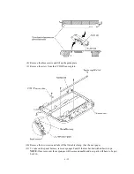
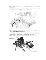
(6) Remove three screws "i" and separate the upper NCU/PS shield from the lower one.
(7) Remove screw "j" to release the AC cord grounding wire from the lower NCU/PS shield.
(8) Remove four screws "k" and lift up the power supply PCB.
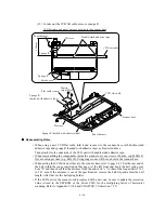
(9) Remove screw "m" and unhook the NCU PCB from the two clips.
Power supply PCB
"i"
Upper NCU/PS shield
"i"
"i"
Tab
Clips
NCU PCB
"m"
Modular
jacks
Openings
Slot
To the
main PCB
Taped side
Power supply harness
(Front)
Hook
AC cord
grounding wire
AC cord
Cord binder
Cutout
"k"
"k"
"k"
"k"
"j"
Lower NCU/PS shield
To the
NCU
PCB
NCU harness
"i, "k," and "m": Taptite, cup S M3x6
"j": Screw, pan (washer) M4x8DB
Reassembling Notes
• Secure the NCU PCB to the lower NCU/PS shield with a screw while pressing the modular
jacks against the openings provided in the lower NCU/PS shield.
• When connecting the NCU harness, be careful with the orientation. Connect the non-taped side
of the harness to the NCU PCB.
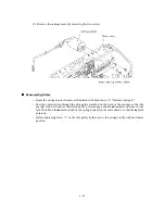
• As shown on the previous page, route the AC cord and its grounding wire. Be sure to secure the
AC cord to the lower NCU/PS shield with a cord binder and fit the grounding wire's ferrite core
over the boss provided on the lower cover.
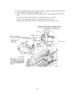
• When securing the FG plate L, be sure to route the paper feed motor harness and ink empty
sensor harness through the cutout provided in the plate.
Summary of Contents for MFC-5200C
Page 1: ...FACSIMILE EQUIPMENT SERVICE MANUAL MODEL MFC5200C MFC890 ...
Page 7: ...CHAPTER 1 PARTS NAMES FUNCTIONS ...
Page 8: ...CHAPTER 1 PARTS NAMES FUNCTIONS CONTENTS 1 1 EQUIPMENT OUTLINE 1 1 1 2 CONTROL PANEL 1 3 ...
Page 13: ...CHAPTER 2 SPECIFICATIONS ...
Page 18: ...2 4 2 1 4 Environmental Condition ...
Page 23: ...CHAPTER 3 INSTALLATION ...
Page 26: ...3 2 3 2 UNPACKING THE MACHINE The equipment consists of the following major components ...
Page 34: ...CHAPTER 4 THEORY OF OPERATION ...
Page 54: ...CHAPTER 5 MAINTENANCE ...
Page 60: ...CHAPTER 6 DISASSEMBLY REASSEMBLY LUBRICATION AND ADJUSTMENT ...
Page 141: ...6 79 2 Separation roller and document feed roller 3 Document ejection roller ...
Page 146: ...6 84 11 Purge shaft EM4 Main chassis ...
Page 151: ...CHAPTER 7 MAINTENANCE MODE ...
Page 160: ...7 8 Scanning Compensation Data List ...
Page 174: ...7 22 Vertical Alignment Check Pattern ...
Page 183: ...CHAPTER 8 ERROR INDICATION AND TROUBLESHOOTING ...
Page 213: ...8 29 4 Close the manual feed cover ...
Page 214: ...MFC5200C MFC890 Appendix 1 Serial No Descriptions ...
Page 216: ... 2 PRINTER HEAD UNIT Location ...
Page 228: ...MFC5200C MFC890 Appendix 3 EEPROM Customizing Codes ...
Page 231: ...MFC5200C MFC890 Appendix 4 Firmware Switches WSW ...
Page 274: ...MFC5200C MFC890 Appendix 5 Re Packing Instructions ...
Page 276: ... 8 Place the machine in the original box with the original packaging material ...
Page 277: ...MFC5200C MFC890 Appendix 6 Wiring Diagram ...
Page 280: ...A Main PCB 1 4 MFC5200C ...
Page 281: ...A Main PCB 2 4 MFC5200C ...
Page 282: ...A Main PCB 3 4 MFC5200C ...
Page 283: ...A Main PCB 4 4 MFC5200C ...
Page 284: ...B Driver PCB 1 2 ...
Page 285: ...B Driver PCB 2 2 ...
Page 286: ...C NCU PCB MFC5200C ...
Page 287: ...D Control Panel PCB 1 2 MFC5200C ...
Page 288: ...D Control Panel PCB 1 2 MFC890 ...
Page 289: ...D Control Panel PCB 2 2 ...
Page 290: ...E Power Supply PCB MFC5200C ...
Page 291: ...F Carriage PCB ...
Page 292: ...G Media PCB 1 2 ...
Page 293: ...G Media PCB 2 2 ...


