DSL LAN Extender 200 User’s Guide
© 2002 Black Box Corporation
Page 30
Appendix C: DSL LAN Extender Routing Models
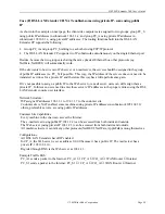
Before configuring the DSL LAN Extender
device, you should take time to understand the DSL LAN
Extender
routing model. This will make planning your network and configuring the DSL LAN Extenders
much easier.
This chapter provides information on the DSL LAN Extender’s routing and bridging capabilities, and
shows some typical application environments. It also will cover the routing related features unique to the
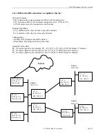
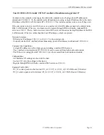
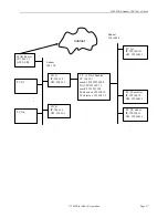
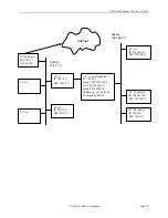
CP side. All example applications will have key parameters shown to make overall picture clear.
Summary of DSL LAN Extender Routing and Bridging Capabilities
A minimum system consists of a DSL LAN Extender
pair; one side is configured as a CO (central office
side) device and the other as a CP (customer side) device. Each side is then connected to an Ethernet
network, and traffic can be bridged/routed between the two sides.
The CO device and CP device are connected by a regular telephone line running xDSL signals, which
carries packets between these two devices with bit rates up to 2.3Mbps (DSL LAN Extender
200) or
7.1Mbps (DSL LAN Extender
800/850). Even though the distance can be as long as 4 or 5 miles, this link
is a dedicated link between two routers (DSL LAN Extender
CO and DSL LAN Extender
CP in this
case). There are not many parameters users need to control and they don’t influence the system level
functionality of routing or bridging. So, a way of looking at the pair of DSL LAN Extenders is to treat it
as a single bridge/router having two Ethernet ports. Each of the ports is capable of doing link level
bridging as well as routing for IP protocol.
Routing and Bridging Features
- Both CO and CP support bridging on Ethernet port
- Both CO and CP support RIP/RIP2 protocol for IP packet routing
- Bridging and RIP routing can be enabled at the same time
Customer Side Features
-CP side supports Network Address Translation (NAT)
-CP side can serve as a Dynamic Host Configuration Protocol (DHCP) server
-CO and CP work together to control the bandwidth of the CP side
Bridging, RIP, and NAT
There are three parameters in the device that users will need to configure to have the device properly
handle packets. They are:
- Bridging Enabled
- RIP Enabled
- NAT Enabled
These parameters result in 8 possible configurations; each of them is a valid setting. The device also
supports the co-existence of a private IP subnetwork and a public IP subnetwork
on the same
Ethernet
network, which is not directly controlled by any parameters. Another factor users might need to consider
is the relationship between CO and CP.
It may seem complicated by just looking at these many combinations. But actually, it’s not.
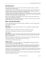
Understanding the basic description of those parameters will make the selection easy.


