DSL LAN Extender 200 User’s Guide
© 2002 Black Box Corporation
Page 32
Example of Applications
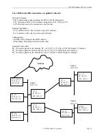
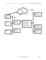
Case (A) Branch Office Connection, no route to outside world
Network Structure:
Three subnetworks connected using two DSL LAN Extender
pairs.
(CO_X denotes a DSL LAN Extender
configured as CO, CP_X as CP.)
Routing Capabilities:
Every machine in the chart can talk to any other machine.
Configurations:
All DSL LAN Extenders have RIP enabled.
All machines IP setting are shown in the chart.
Example Traffic Path:
PC_A1 sends a packet to PC_B1:
PC_A1
1
→
CP_A
→
CO_A
→
CO_B
→
CP_B
→
PC_B1
PC_X1
IP: 194.1.1.11
GW: 194.1.1.1
CO_A
IP: 194.1.1.1
GW: 0.0.0.0
CO_B
IP: 194.1.1.2
GW: 0.0.0.0
CP_A
IP: 194.1.2.1
GW: 0.0.0.0
CP_B
IP: 194.1.3.1
GW: 0.0.0.0
PC_A1
IP: 194.1.2.2
GW: 194.1.2.1
.
.
.
.
.
.
Subnet
194.1.2.0
Subnet
194.1.1.0
PC_X1
IP: 194.1.1.12
GW: 194.1.1.1
Subnet
194.1.3.0
PC_B1
IP: 194.1.3.2
GW: 194.1.3.1
.
.
.
.
.
.

