DSL LAN Extender 200 User’s Guide
© 2002 Black Box Corporation
Page 3
Quick Start
This section provides the basic steps to follow to set up and configure your DSL LAN Extender devices.
It is intended for users with network experience who don’t need the detailed instructions in this user’s
guide to set up and configure the DSL LAN Extender 200.
You must perform the steps below for both the DSL LAN Extender CO and CP devices.
1.
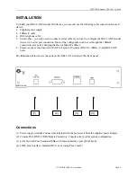
Connect the DSL LAN Extender device to your network via its 10Base-T port.
2.
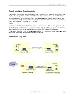
Connect the DSL LAN Extender device to the DSL line via its LINE port.
3.
Attach a null-modem or straight serial cable to the serial port on a PC; attach the other end to the DSL
LAN Extender device’s Console (RS-232) port.
4.
Connect the power supply to a grounded outlet and insert the power supply connector into the DSL
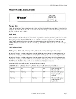
LAN Extender device’s power port. The LEDs on the device’s front panel should flash while the device
performs its startup diagnostic tests.
5.
Configure the following settings for a terminal-emulation program (ProComm Plus recommended) on
the PC you connected to the DSL LAN Extender device’s Console port:
•
Data rate:
Specify console data rate up to 38400; the DSL LAN Extender device will
automatically adapt to the rate you specify
•
Terminal type:
VT 100
•
Data bits:
8
•
Parity bits:
None
•
Stop bits:
1
•
Flow Control:
None
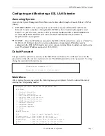
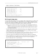
6. After you connect the PC to the DSL LAN Extender device, the main menu appears by pressing
<Enter> a few times. Select the DSL Status/ Configuration option from the Main Menu. When
prompted for the password, enter <
password>.
7. One of the DSL LAN Extender
devices is pre-configured as CO and the other device is pre-
configured as a CP. Select the DSL and Status Configuration menu option, and you can change the
configuration to either CO or CP.
8. The device is pre-configured with the highest allowed line rate. For the CO device, use the Line Rate
selection option to select successively lower line rates until the two devices link up. You do not need
to change the line rate defined for the CP device, as it will automatically adapt to the rate selected for
the CO device.
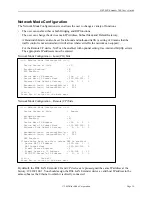
9. Select the Network Mode Configuration option from the Main Menu.
Define the setting of Bridging Enabled and RIP Enabled functions. If RIP is enabled, then select
Device Main IP Address and its Subnet Mask address. It is optional to define the Default Gateway.
10. Set the Bandwidth control for Outbound and Inbound traffic rates in Kbps. (A setting of 0 is
equivalent to no bandwidth control.)
11. For CP devices only, the NAT enabled option can be activated. Define the device’s IP address for
NAT and its subnet mask.
12. Configure the optional IP addresses for E-mail server and HTTP/FTP server.
13. Select DHCP Status/Configuration option from the Main Menu to configure IP address range for
DHCP and DNS servers.

