background image

                                                                                                                                                   DSL LAN Extender 200 User’s Guide 


 © 2002 Black Box Corporation 

Page 9 

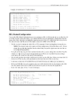
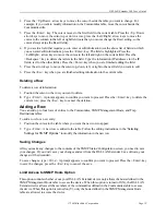
    Example of Sub-Menu # 2: Traffic Statistics  


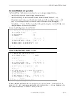
DSL Status/Configuration 

You use the DSL Status/Configuration screen to configure a DSL LAN Extender device as either the CO 
or CP device. This screen also allows you to define the DSL line rate and displa ys information about the 
status of the DSL connection, including the operation mode of CO or CP, whether the link is up or down, 
line rate selected, actual line rate and the signal to noise ratio (SNR) of the DSL line. 

The Device can be changed to either CO or CP by pressing <Enter> and toggling between the two.   

NOTE

: The devices work only in pairs, with one configured as CO and the other as CP.  This is 

already factory defaulted and this function should only be used for replacement devices that are 
not configured appropriately. 

Using the arrow keys to get to the Line Rate Selection line, you can change the Line Rate. Press the 
<Enter> or <Space> key to select the appropriate speed. There are 9 available line rates settings: 
2320, 2064, 1552, 1040, 784, 528, 400, 272 and 144 Kbps. 

The Actual Line Rate shows the actual line rate in effect on the DSL line. When you connect the CO 
device to a CP device, they will synchronize on the lower line rate of the two devices. 

Link status is shown as UP or DOWN when CO and CP devices are linked up or not linked up. 

DSL Line SNR (dB) shows the signal-to-noise ratio (in Decibels) for the received signal on the DSL 
line. The normal values for 24 AWG and 26 AWG wire pairs are shown in the Appendix E. 

Note: You must press <Ctrl-s> to save all changes. 


===== DSL Status/Configuration ===== 


 . The Device Configured as  :  CP        Link Status :  Down 
 . Line Rate Selection(Kbps) :  2320 
 . Actual Line Rate(Kbps)    :  0 
   (Determined by lower rate of both sides) 
 . DSL Line SNR(dB)          : 0.0 


 Ctrl-s            Save all 
 Press Esc to return to the main menu 


===== Traffic Statistics ===== 


 . Ethernet Packets Received :        375 
 . Ethernet Packets Sent     :        375 
 . Ethernet Tx+Rx  Errors    :          0 
 . DSL Line Packets Received :        375  
 . DSL Line Packets Sent     :        375 
 . DSL Line Rx Packet Errors :          0 


 . Current Error: (no error) 


 Press '0' to reset the traffic statistics. 
 Press Esc to return to the main menu 
 

Summary of Contents for DSL LAN Extender 200

Page 1: ... 321 0746 Technical support and fax orders 24 hours a day 7 days a week Phone orders 24 hours 7 A M Monday to midnight Friday Saturday 8 to 4 Eastern Mail order Black Box Corporation 1000 Park Drive Lawrence PA 15055 1018 Web site http www blackbox com E mail info blackbox com CUSTOMER SUPPORT INFORMATION ...

Page 2: ...ss Black Box Corp 1000 Park Drive Lawrence PA 15055 1018 Phone 724 746 5500 Fax 800 321 0746 URL www blackbox com EMAIL info blackbox com Notice Black Box is a registered trademark of Black Box Corporation All other company or product names mentioned are the property of their respective owners All rights reserved ...

Page 3: ...igital apparatus does not exceed the Class A limits for radio noise emission from digital apparatus set out in the Radio Interference Regulation of the Canadian Department of Communications Le présent appareil numérique n émet pas de bruits radioélectriques dépassant les limites applicables aux appareils numériques de la classe A prescrites dans le Règlement sur le brouillage radioélectrique publi...

Page 4: ...ción debe ser tomada de tal manera que la tierra fisica y la polarización del equipo no sea eliminada 13 Los cables de la fuente de poder deben ser guiados de tal manera que no sean pisados ni pellizcados por objetos colocados sobre o contra ellos poniendo particular atención a los contactos y receptáculos donde salen del aparato 14 El equipo eléctrico debe ser limpiado únicamente de acuerdo a las...

Page 5: ...47 63Hz AC unless otherwise specified Before inserting the AC power plug into a wall socket be certain that your electrical power is within the correct range of values 5 Do not operate the DSL LAN Extender device beyond the temperature and humidity range specified see specifications section 6 Do not place near or over sources of heat such as a heater or radiator Do not expose this unit to rain or ...

Page 6: ...ask 11 Defining the Ethernet Side Default Gateway 11 Bandwidth Control 11 DHCP Status Configuration 13 SNMP Configuration 17 Bridge Filtering 24 Password Change 24 Software Download 24 TROUBLESHOOTING 27 Table 1 Troubleshooting Procedure 27 APPENDIX A TECHNICAL SPECIFICATIONS 28 Table 2 Technical Specifications 28 Table 3 Line Rate at Different Cable Lengths 28 APPENDIX B PORT PIN LAYOUTS 29 Conso...

Page 7: ...DSL line interface which can achieve high transmission quality comparable to fiber optic BER without repeaters up to 5 5 miles 8 8 Km Featuring a compact design for easy installation and combining its high speed symmetrical rate and longer local loop reach a DSL LAN Extender 200 is an ideal solution for campus networks remote LAN interconnection and high speed Internet access for businesses and co...

Page 8: ...erial console port or Ethernet port via TFTP Stand alone compact design with rack mount kit option Use industry standard CAP Carrierless Amplitude Phase Modulation line coding for superior performance and low power consumption Support for the following protocols ARP DHCP ICMP IP NAT RIP 1 RIP 2 SNMP TCP UDP telnet and TFTP Package Contents The list below shows what is included in your DSL LAN Exte...

Page 9: ...e Stop bits 1 Flow Control None 6 After you connect the PC to the DSL LAN Extender device the main menu appears by pressing Enter a few times Select the DSL Status Configuration option from the Main Menu When prompted for the password enter password 7 One of the DSL LAN Extender devices is pre configured as CO and the other device is pre configured as a CP Select the DSL and Status Configuration m...

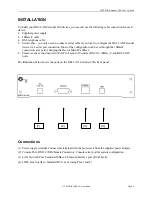
Page 10: ...on can be set through the 10BaseT connection except for changing the Device Main IP address Please see the section below for Port Pin Layout of Console RS 232 10Base T and DSL LINE ports The illustration below shows the ports on the DSL LAN Extender 200 s back panel Connections 1 Power supply terminal Connect this terminal with the power jack from the supplied power adapter 2 Console Port RS 232 D...

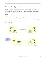
Page 11: ...bridged taps on it For example Pacific Bell s Local Area Data Channels LADC use USOC code to specify a 2 wire dry line as T6E2D NOTE The term non loaded or non loaded coils means no passive lowpass filter for voice spectrum on the line With a lowpass filter the loop is used for voice signals only the high frequency spectrum of signals above 4Khz will be filtered out and the loop cannot be used for...

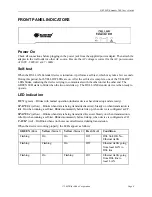
Page 12: ...ice is then ready to operate LED Indication RUN green Blinks with normal operation indicates devices have linked up and are ready STATUS 1 yellow Blinks when data is being transmitted received Steady on when transmission is idle On when running a self test Blinks momentarily before link up when device is configured as CP STATUS 2 yellow Blinks when data is being transmitted received Steady on when...

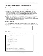
Page 13: ...net command can be used The default IP address assigned is 192 168 100 1 Default Password The password is required to access any of the Main Menu s sub menus You will need to re enter the password each time the device is restarted or reset The default password is set to password You may change the password in the main menu Main Menu After entering the correct password the following message is disp...

Page 14: ...nit s firmware has been corrupted In this case you have to reload the firmware Remember each new firmware version has a different checksum EXAMPLE OF SUB MENU 1 SYSTEM INFORMATION Traffic Statistics The Statistics sub menu 2 provides traffic statistics from to the Ethernet port and from to the DSL port Ethernet Packets Received Number of Ethernet packets that have been received from the LAN Ethern...

Page 15: ...e key to select the appropriate speed There are 9 available line rates settings 2320 2064 1552 1040 784 528 400 272 and 144 Kbps The Actual Line Rate shows the actual line rate in effect on the DSL line When you connect the CO device to a CP device they will synchronize on the lower line rate of the two devices Link status is shown as UP or DOWN when CO and CP devices are linked up or not linked u...

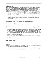
Page 16: ...factory 192 168 100 1 You should assign the DSL LAN Extender device a valid host IP address in the same subnet as the Ethernet to which it is directly connected Network Mode Configuration Device Serves at Side CO Bridging Enabled N RIP Enabled N Device Main IP Address 194 1 1 2 Device Main IP Subnet Mask 255 255 255 0 Ethernet Side Default Gateway 194 1 1 1 Bandwidth Limit Outbound Kbit s 256 Band...

Page 17: ... see Appendix C for examples of setting the IP parameters for different network environments Bandwidth Control The bandwidth control feature allows you to control the bandwidth allocated for information going out to the remote side and coming into the local LAN side Users who mostly download information from the Web for example would probably want to increase the amount of inbound traffic On the o...

Page 18: ...ith NAT turned on the outside world only sees one public IP address the DSL side IP address for all the machines The NAT option also enhances the security of your network because only a single IP address is presented to the world not every computer s IP address This makes it harder for hackers to access the computers on your network To turn on the NAT feature select Y for the NAT Enabled option an...

Page 19: ...main IP address of the CP device If the NAT option is enabled you can use private IP addresses for all the computers including E mail and HTTP FTP servers on the local LAN as long as they are in the same subnet as the NAT IP address All of these computers have to point their default gateway to the NAT IP address of the CP device DHCP Status Configuration The Dynamic Host Configuration Protocol DHC...

Page 20: ... you could define the following DHCP range 1 2 3 4 to 1 2 3 30 To specify the DHCP IP address range 1 Use the arrow keys to position the cursor beside the first DHCP Range field Press the Enter key The field is highlighted 2 Type the starting IP address for the range Press the Enter key when you are finished typing the first address 3 Press the Right arrow key to move the cursor to the next DHCP R...

Page 21: ...or the hours Press the Enter key The field is highlighted 4 Type the desired number of hours up to 99 Press the Enter key when you are finished Type Ctrl s to save the new settings You can display status information about the DHCP clients and also delete them Configuring DHCP Clients To allow machines on your local LAN to receive their IP information from the DSL LAN Extender CP device you must co...

Page 22: ... Press the Esc key to move the cursor out of the DHCP Lease Status field Deleting DHCP Clients In general if you want to release a client s IP address you should release them using the operating system s network software see the Implementing New DHCP Settings for information on how to release clients However if you cannot do this for some reason for example if the machine assigned the IP address i...

Page 23: ...rogram you are using so you should check the documentation that came with your SNMP management software for instructions on how to install MIBs Below is some information describing how you can get the latest MIB files and how to install them In an effort to continually improve our products Black Box will update the DSL LAN Extender MIB files and post the updated MIB files on the Black Box Web site...

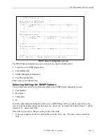
Page 24: ... For all the other fields including the Limit Access to SNMP Hosts field you simply need to move the cursor beside the desired option and then press the Enter key to display the desired setting Y option turned on N option turned off Follow the steps below to change a setting in one of the tables 1 If the cursor appears inside one of the tables press the Esc key The cursor moves outside the table S...

Page 25: ... delete a row of information 1 Position the cursor in the row you want to delete 2 Type Ctrl d A prompt appears to confirm you want to proceed Press the Enter key to delete the current row press the Esc key to cancel the deletion Adding a Row You can add up to four rows of entries to the Communities SNMP Management Hosts and Trap Destinations tables To add a row for a new entry 1 Position the curs...

Page 26: ... disallow N members of the community to modify the device s configuration You designate the members of the community you want to be able to access the device in the SNMP Management Hosts table Specifying Who Can Access the Device You can specify the hosts on the network who will be allowed to access the device You use the SNMP Management Hosts table to do this This feature adds an additional level...

Page 27: ...mmunity must be configured to receive trap information that is Trap Y The host must be correctly defined in the Trap Destinations table SNMP Features Supported The main features of the DSL LAN Extender devices SNMP support are as follows Supports standard MIB II MIBs as defined in RFC 1213 Supports two Black Box private MIBs blackbox mib and extender mib These features are described below Standard...

Page 28: ...face DB 9 for DSL LAN Extender 800 850 LS RS 422 Low Speed Serial Interface DB 25 M 34 Manchester 34 pin V 35 interface Black Box Private MIBs Black Box provides two private MIBs for the DSL LAN Extender devices a Black Box system MIB blackbox mib and a Black Box DSL LAN Extender MIB extender mib You can find the most current information about the MIBs in the MIB files themselves Just use a text e...

Page 29: ...icalIfGroup This group provides information associating the logical DSL interfaces to the physical interfaces For the DSL LAN Extender 200 model there is a one to one mapping between the logical and physical interfaces On the other hand for the DSL LAN Extender 800 model one logical interface namely WaiDSL is mapped to two physical interfaces RADSL This table clearly shows the relationship between...

Page 30: ...less System must be rebooted after entering the new password to be valid Software Download Console Port Download Via RS 232 Press 7 from the main menu to access the Software Download sub menu Have your new firmware file ready before selecting this function Enter Y to continue or press Esc to go back to the main menu Instructions are displayed as shown below Follow these instructions to set up your...

Page 31: ...he download process Download via Ethernet TFTP DOS Version Have the new software ready and know the file location Make sure you have the TFTP command file on your system 1 Make sure your PC has an Ethernet connection to the box 2 Start a DOS session from Windows 95 or Windows NT 3 Assuming the box s IP address is 10 0 0 1 and the file you want to download is wcs10002 1 type tftp i 10 0 0 1 put wcs...

Page 32: ...ashing as packets are forwarded then either the PC doesn t have a good Ethernet connection to the box or the IP address you entered is incorrect If the green yellow yellow LEDs keep circulating then the download has failed in the middle You have to reset the box by powering off and on the box and see the status of last download If the problem happened pretty early and the flash ROM has not been to...

Page 33: ... Check connections Red light ON after power up Bad connection Check phone jack cable Green light all LED steady ON System Down Try Reset by unplugging plugging the power jack Both yellow lights OFF after power up reset Bad internal connection Call technical support for help No Response from LAN port Possibly wrong 10Base T cable being used Use straight 10Base T cable to hub or switch Use crossed 1...

Page 34: ...Amp Environmental Humidity Operating Temp Storage Temp Up to 95 32 to 122 F 4 to 158 F Physical Dimensions H 1 3 4 x W 12 x D 7 3 4 Table 3 Line Rate at Different Cable Lengths NOTE The reach distance can change significantly due to line quality and noise conditions Symmetrical Line Rate Kbps 26 AWG Kft km 24 AWG Kft km Configuration No 1 2320 10 3 3 14 13 7 4 17 Configuration No 2 2064 11 0 3 35 ...

Page 35: ... A 10Base T RJ 45 Port Pin Layout RJ 45 PIN Direction PIN Assignment 1 OUTPUT TXD 2 OUTPUT TXD 3 INPUT RXD 4 N A N A 5 N A N A 6 INPUT RXD 7 N A N A 8 N A N A Note You must use straight 10Base T cable to connect to a Hub Switch etc To connect to a PC Router etc you must use a crossed 10Base T cable xDSL Line RJ 11 Port Pin Layout PIN Direction PIN Assignment 1 N A N A 2 N A N A 3 Tx Rx Data 4 Tx R...

Page 36: ...nd DSL LAN Extender CP in this case There are not many parameters users need to control and they don t influence the system level functionality of routing or bridging So a way of looking at the pair of DSL LAN Extenders is to treat it as a single bridge router having two Ethernet ports Each of the ports is capable of doing link level bridging as well as routing for IP protocol Routing and Bridging...

Page 37: ...re IP Routers including other DSL LAN Extenders This parameter should also be enabled on the CO side if it is enabled on the CP side This option can also be turned on even if there is no IP router on the local subnet NAT Enabled Enable this option if you will use the device s Network Address Translation NAT feature This feature allows a number of machines to use private IP addresses and to share a...

Page 38: ... in the chart can talk to any other machine Configurations All DSL LAN Extenders have RIP enabled All machines IP setting are shown in the chart Example Traffic Path PC_A1 sends a packet to PC_B1 PC_A1 1 CP_A CO_A CO_B CP_B PC_B1 PC_X1 IP 194 1 1 11 GW 194 1 1 1 CO_A IP 194 1 1 1 GW 0 0 0 0 CO_B IP 194 1 1 2 GW 0 0 0 0 CP_A IP 194 1 2 1 GW 0 0 0 0 CP_B IP 194 1 3 1 GW 0 0 0 0 PC_A1 IP 194 1 2 2 GW...

Page 39: ...All DSL LAN Extenders have RIP enabled All machines IP setting are shown in the chart Example Traffic Path PC_A1 sends a packet to the Internet PC_A1 CP_A CO_A WAN Router Internet PC_X1 sends a packet to the Internet PC_X1 CO_A WAN Router Internet PC_Xn sends a packet to the Internet PC_Xn CO_B WAN Router Internet PC_X1 IP 194 1 1 11 GW 194 1 1 2 CO_A IP 194 1 1 2 GW 194 1 1 1 CO_B IP 194 1 1 3 GW...

Page 40: ...nfigurations All DSL LAN Extenders have RIP enabled All machines IP setting are shown in the chart Example Traffic Path PC_A1 sends a packet to the Internet PC_A1 CP_A CO_A WAN Router Internet PC_X1 sends a packet to the Internet PC_X1 CO_A WAN Router Internet PC_X1 server IP 194 1 1 11 GW 194 1 1 2 CO_A IP 194 1 1 2 GW 194 1 1 1 CO_B IP 194 1 1 3 GW 194 1 1 1 CP_A IP 194 1 2 1 GW 0 0 0 0 CP_B IP ...

Page 41: ...tting are shown in the chart All DSL LAN Extenders at 194 1 1 0 CO_A CO_B CP_ISP can be replaced by an IP Address Translator Example Traffic Path PC_A1 sends to Internet PC_A1 CP_A CO_A CP_ISP CO_ISP WAN Router Internet PC_X1 sends to Internet PC_X1 CO_A CP_ISP CO_ISP WAN Router Internet PC_Xn sends to Internet PC_Xn CP_ISP CO_ISP WAN Router Internet Subnetwork 194 1 0 0 ISP POP in CO PC_X1 IP 194...

Page 42: ...s having IP address of the DSL LAN Extender CP device rather than their real IP addresses which are private Network Structure ISP assigns IP addresses 194 1 1 1 to 194 1 1 7 to the customer site Customer site has NAT enabled all machines using private IP addresses in subnetwork 192 168 1 0 Customer Site Capabilities A single IP address serves the whole group including e mail and Web servers The e ...

Page 43: ... NAT Enabled IP 194 1 2 1 mask 255 255 255 248 NAT IP 192 168 1 1 mask 255 255 255 0 Mail server 192 168 1 2 Web server 192 168 1 3 PC_A1 IP 192 168 1 11 GW 192 168 1 1 Subnet 192 168 1 0 Subnet 194 1 1 0 PC_Xn PC_S1 email sv IP 192 168 1 2 GW 192 168 1 1 WAN Router IP 194 1 1 1 GW 0 0 0 0 Internet PC_S2 web sv IP 192 168 1 3 GW 192 168 1 1 ...

Page 44: ...ittle performance gain If it s not possible to assign a public IP to the Web server or e mail server users can still assign them a private IP In this case users need to enter these servers IP addresses to the proper entries using the DSL LAN Extender console user interface Network Structure ISP assigns IP addresses 194 1 1 1 to 194 1 1 7 to the customer site Customer site is NAT enabled some machi...

Page 45: ...P_A NAT Enabled IP 194 1 2 1 mask 255 255 255 248 NAT IP 192 168 1 1 mask 255 255 255 0 Mail server 192 168 1 10 Web server 0 0 0 0 PC_A1 IP 192 168 1 11 GW 192 168 1 1 Subnet 192 168 1 0 Subnet 194 1 1 0 PC_Xn PC_S1 email sv IP 192 168 1 10 GW 192 168 1 1 WAN Router IP 194 1 1 1 GW 0 0 0 0 Internet PC_S2 web sv IP 194 1 2 3 GW 194 1 2 1 ...

Page 46: ...ask Default gateway 2 Change the PC s network settings to the following IP address 192 168 100 2 you can specify any integer between 2 and 254 for the last number Subnet mask 255 255 255 0 Default gateway 192 168 100 1 3 Restart the PC to implement these changes NOTE If your network uses TCP IP as the primary network protocol after you make the changes described above and then restart the PC it s ...

Page 47: ...30 2 33 0 35 0 39 2 11000 30 0 31 9 37 7 12000 26 8 29 1 36 6 13000 25 7 34 2 14000 31 9 15000 28 8 Normal Signal to Noise Ratio Table for 24 AWG wire pair SNR Values at Different Speeds dB Distance ft 2320 Kbps 2060 Kbps 1552 Kbps 1040 Kbps 528 Kbps 6000 38 8 40 2 41 1 41 1 42 7 7000 37 7 38 4 39 4 40 2 40 3 8000 37 0 38 1 39 1 39 0 40 0 9000 35 8 37 7 38 5 38 3 39 6 10000 33 7 37 2 37 7 37 7 38 ...

Page 48: ... References The firmware version is _____________________________ The console management password is ________________ The configuration on the MSDSL unit is ______________ For Ethernet interface The Ethernet Address assigned to the MSDSL device is _____________________ The IP Address assigned to the MSDSL device is ________________________________________ Remote Unit References The firmware versio...

Page 49: ...echnical Support Information Black Box Corporation 1000 Park Drive Lawrence PA 15055 Technical Support Phone 724 746 5500 Fax 800 321 0746 Email info blackbox com Response within one working day URL www blackbox com for additional information diagrams and firmware updates ...

Page 50: ... Copyright 2002 Black Box Corporation All rights reserved 1000 Park Drive Lawrence PA 15055 1018 724 746 5500 Fax 800 321 0746 ...

Reviews: