


Operation – 3
3–1
3
Operation
3.1
Front Panel Controls ............................................................................ 3–1
3.2
Initial Setup Procedure/Settings .......................................................... 3–3
3.3
Status/Metering ................................................................................... 3–8
3.4
Target History ...................................................................................... 3–9
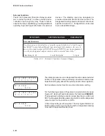
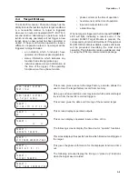
Alphanumeric Display
To assist the operator in setting and interrogating
the relay locally, the display shows menus which
guide the operator to the desired function or setpoint
value. These menus consist of two lines. The bottom
line lists lower case abbreviations of each menu
selection with the chosen menu selection shown in
uppercase. The top menu line provides a description
of the chosen menu selection.
Screen Blanking
The display will automatically blank after exiting
from the Main Menu, or from any screen after five
(5) minutes of unattended operation. To wake up
the display, the user must press any key except
EXIT.
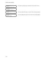
Arrow Push-buttons
The left and right arrow buttons are used to choose
among menu selections displayed. When entering
values, the left and right arrow buttons are used to
select the digit (by moving the cursor) of the
displayed setpoint that will be increased or decreased
by the use of the up and down buttons.
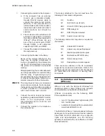
This chapter contains information that describes
the operation, direct setting, and configuration of
the M-3931 Human Machine Interface Module (HMI)
and M-3925 Target modules. It further describes the
procedures for entering all required data to the relay.
Included in this chapter is a description of the
process necessary for review of setpoints and timing,
monitoring function status and metering quantities,
viewing the target history, and setup of the
oscillograph recorder.
3.1
Front Panel Controls
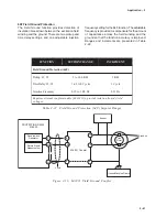
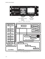
The relay has been designed to be set and
interrogated locally with the optional HMI panel. An
integral part of this design is the layout and function
of the front panel indicators and controls, illustrated
in Figure 3-1.
Summary of Contents for M-3425
Page 1: ...Instruction Book M 3425 Generator Protection ...
Page 14: ... 13 M 3425 Generator Protection Relay Figure 1 External Connections ...
Page 33: ...x M 3425 Instruction Book This Page Left Intentionally Blank ...
Page 89: ...M 3425 Instruction Book 2 52 This Page Left Intentionally Blank ...
Page 125: ...1 3 A B C M 3425 Instruction Book 4 26 This Page Left Intentionally Blank ...
Page 187: ...M 3425 Instruction Book 6 50 This Page Left Intentionally Blank ...
Page 207: ...M 3425 Instruction Book C 4 This Page Left Intentionally Blank ...
Page 209: ...D 2 M 3425 Instruction Book Figure D 1 Volts Hz 24 Inverse Curve Family 1 Inverse Square ...
Page 210: ...Inverse Time Curves Appendix D D 3 Figure D 2 Volts Hz 24 Inverse Family Curve 2 ...
Page 211: ...D 4 M 3425 Instruction Book Figure D 3 Volts Hz 24IT Inverse Curve Family 3 ...
Page 212: ...Inverse Time Curves Appendix D D 5 Figure D 4 Volts Hz 24IT Inverse Curve Family 4 ...
Page 215: ...D 8 M 3425 Instruction Book Figure D 5 Definite Time Overcurrent Curve ...
Page 216: ...Inverse Time Curves Appendix D D 9 Figure D 6 Inverse Time Overcurrent Curve ...
Page 217: ...D 10 M 3425 Instruction Book Figure D 7 Very Inverse Time Overcurrent Curve ...
Page 218: ...Inverse Time Curves Appendix D D 11 Figure D 8 Extremely Inverse Time Overcurrent Curve ...
Page 223: ...D 16 M 3425 Instruction Book This Page Intentionally Left Blank ...


