


Installation – 5
5–1
5
Installation
5.1
General Information ............................................................................. 5–1
5.2
Mechanical/Physical Dimensions ........................................................ 5–1
5.3
Commissioning Checkout .................................................................... 5–8
5.4
Circuit Board Switches and Jumpers ..................................................5–10
5.1
General Information
The person or group responsible for the installation
of the relay will find herein all mechanical information
required for physical installation, equipment ratings,
and all external connections in this chapter. For
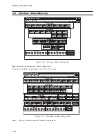
reference, the Three-Line Connection Diagram is
repeated from Chapter 2, Application. Further, a
commissioning checkout procedure is outlined using
the HMI option to check the external CT and VT
connections. Additional tests which may be desirable
at the time of installation are described in Chapter
6, Testing.
■
■
■
■
■
NOTE: Prior to installation of the equipment, it
is essential to review the contents of
this manual to locate data which may be
of importance during installation
procedures. The following is a quick
review of the contents in the chapters of
this manual.
It is suggested the terminal connections illustrated
here be transferred to
station one-line wiring and
three-line connection diagrams,
station panel
drawings and
station DC wiring schematics.
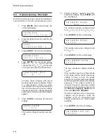
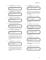
If during the commissioning of the M-3425 Generator
Protection Relay, additional tests are desired,
Chapter 6, Testing, may be consulted.
The operation of the relay, including the initial setup
procedure, is described in Chapter 3, Operation,
for HMI front panel users and in Chapter 4, Remote
Operation, when using a personal computer. Section
3.1, Front Panel Controls, details the front panel
controls. Section 3.2, Initial Setup
Procedure/Settings, details the HMI setup
procedure. This includes details necessary for input
of the communications data, unit setup data,
configure relays data, the individual setpoints and
time settings for each function, and oscillograph
recorder setup information. Section 3.3,
Status/Metering, guides the operator through the
checkout status procedures, including monitoring
the status and viewing the target history.
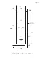
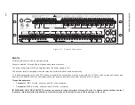
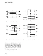
5.2
Mechanical/Physical
Dimensions
Figures 5-1, 5-2, 5-3, and 5-4 contain physical
dimensions of the relay that may be required for
mounting the unit on a rack.
Summary of Contents for M-3425
Page 1: ...Instruction Book M 3425 Generator Protection ...
Page 14: ... 13 M 3425 Generator Protection Relay Figure 1 External Connections ...
Page 33: ...x M 3425 Instruction Book This Page Left Intentionally Blank ...
Page 89: ...M 3425 Instruction Book 2 52 This Page Left Intentionally Blank ...
Page 125: ...1 3 A B C M 3425 Instruction Book 4 26 This Page Left Intentionally Blank ...
Page 187: ...M 3425 Instruction Book 6 50 This Page Left Intentionally Blank ...
Page 207: ...M 3425 Instruction Book C 4 This Page Left Intentionally Blank ...
Page 209: ...D 2 M 3425 Instruction Book Figure D 1 Volts Hz 24 Inverse Curve Family 1 Inverse Square ...
Page 210: ...Inverse Time Curves Appendix D D 3 Figure D 2 Volts Hz 24 Inverse Family Curve 2 ...
Page 211: ...D 4 M 3425 Instruction Book Figure D 3 Volts Hz 24IT Inverse Curve Family 3 ...
Page 212: ...Inverse Time Curves Appendix D D 5 Figure D 4 Volts Hz 24IT Inverse Curve Family 4 ...
Page 215: ...D 8 M 3425 Instruction Book Figure D 5 Definite Time Overcurrent Curve ...
Page 216: ...Inverse Time Curves Appendix D D 9 Figure D 6 Inverse Time Overcurrent Curve ...
Page 217: ...D 10 M 3425 Instruction Book Figure D 7 Very Inverse Time Overcurrent Curve ...
Page 218: ...Inverse Time Curves Appendix D D 11 Figure D 8 Extremely Inverse Time Overcurrent Curve ...
Page 223: ...D 16 M 3425 Instruction Book This Page Intentionally Left Blank ...


