


6–15
Testing – 6
6.4
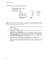
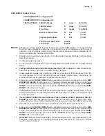
Functional Test Procedures
This section details test quantities, inputs and
procedures for testing each relay function. The
purpose is to confirm the functions’ designated
output operation, the accuracy of the magnitude
pickup settings, and the accuracy of time delay
settings. Whereas the first test described, “Power
On Self Test”, does not require electrical quantity
inputs, all other functional tests do require inputs,
and the necessary connection configurations are
noted.
In all test descriptions, a process for calculating
input quantities to test the actual settings of the
function will be given if needed. In many test cases,
it will be necessary to disable other functions not
being tested at the time. This action is to prevent
the operation of multiple functions with one set of
input quantities, which could cause confusion of
operation of outputs or timers. The complete
description of the method to disable/enable functions
may be found in detail in Section 3.2, Configure
Relay Data subsection or Chapter 4, Remote
Operation. The complete description of the method
to install setting quantities may be found in Section
3.2, Setpoints and Time Settings subsection.
It is desirable to
record and confirm the actual
settings of the individual functions before beginning
test procedures. Use Figure A-3, Functional
Configuration Record Form and Figure A-4, Setpoint
& Timing Record Form, found in Appendix A,
Configuration Record Forms, to record settings. It
is also possible to download the relay settings into
a file using IPScom
®
.
It may be desirable to program all test settings in an
alternate profile, or to save the relay settings in
IPScom to preserve desired setup.
The tests are described in this section in ascending
function number order as used in Chapter 2,
Application. Depending on which functions are to
be tested at a given time, an order may be
determined with the aid of Table 6-1, Functions to
Disable When Testing. This may result in the fewer
changes in connections and disable/enable
operations.
During the lifetime of the relay, testing of individual
functions due to changes in application settings will
be more likely than an overall testing routine. An
index of the individual test procedures is illustrated
at the beginning of this chapter.
■
■
■
■
■
NOTE: Care must be taken to reset or enable
any functions that have been changed
from their intended application settings
when the test procedures are complete.
Many options for test sequences and methods are
possible. As an example, the operation of the output
contacts can be tested along with the operation of
the LEDs in the Diagnostic Test Procedures. The
operation of the output contacts may also be
confirmed with the LED and function operation during
Functional Test Procedures, if desired.
If timer quantities are to be checked, the timer must
be activated by the appropriate output contacts.
The contact pin numbers are enumerated in Table
6-2,
Output Contacts.
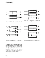
It is suggested that copies of the following be made
for easy referral during test procedures:
Input Configurations – pg 6–4
Output Contact Numbers – pg 6–6
Relay Configuration Table – pg A–2
Setpoint & Timing Record Form – pg A–9
Summary of Contents for M-3425
Page 1: ...Instruction Book M 3425 Generator Protection ...
Page 14: ... 13 M 3425 Generator Protection Relay Figure 1 External Connections ...
Page 33: ...x M 3425 Instruction Book This Page Left Intentionally Blank ...
Page 89: ...M 3425 Instruction Book 2 52 This Page Left Intentionally Blank ...
Page 125: ...1 3 A B C M 3425 Instruction Book 4 26 This Page Left Intentionally Blank ...
Page 187: ...M 3425 Instruction Book 6 50 This Page Left Intentionally Blank ...
Page 207: ...M 3425 Instruction Book C 4 This Page Left Intentionally Blank ...
Page 209: ...D 2 M 3425 Instruction Book Figure D 1 Volts Hz 24 Inverse Curve Family 1 Inverse Square ...
Page 210: ...Inverse Time Curves Appendix D D 3 Figure D 2 Volts Hz 24 Inverse Family Curve 2 ...
Page 211: ...D 4 M 3425 Instruction Book Figure D 3 Volts Hz 24IT Inverse Curve Family 3 ...
Page 212: ...Inverse Time Curves Appendix D D 5 Figure D 4 Volts Hz 24IT Inverse Curve Family 4 ...
Page 215: ...D 8 M 3425 Instruction Book Figure D 5 Definite Time Overcurrent Curve ...
Page 216: ...Inverse Time Curves Appendix D D 9 Figure D 6 Inverse Time Overcurrent Curve ...
Page 217: ...D 10 M 3425 Instruction Book Figure D 7 Very Inverse Time Overcurrent Curve ...
Page 218: ...Inverse Time Curves Appendix D D 11 Figure D 8 Extremely Inverse Time Overcurrent Curve ...
Page 223: ...D 16 M 3425 Instruction Book This Page Intentionally Left Blank ...


