


M-3425 Instruction Book
2–18
32
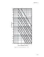
Directional Power, 3-Phase
The directional power function can provide protection
against both generator motoring and overload. It
provides two power setpoints, each with a magnitude
setting and a time delay. The Forward Power direction
(power flow to system) is automatically chosen
when the pickup setting is positive and the Reverse
Power direction (power flow to generator) is
automatically chosen when the pickup setting is
negative. The range, as shown is from –3.000 PU to
3.000 PU where 1.0 PU is equal to the generator
MVA rating. Normalized PU power flow
measurements are based on Nominal Voltage and
Nominal Current setting, as shown in Section 2.1,
Configuration, Relay System Setup.
When the Low Forward Power setting is disabled,
the relay will trip in the forward direction (positive
programmed Pickup setting). This configuration can
be used for overload protection, providing either
alarm or tripping. Again, when the Low Forward
Power setting is disabled, the relay will trip in the
reverse direction (negative programmed Pickup
setting), when the measured real power is less than
(more negative) or equal to the Pickup setting. This
configuration can be used for sequential tripping
when power is below the setting. The ranges and
increments are presented in Table 2-6.
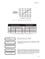
When tripping is desired for reverse power flow or
very small forward power values, the Low Forward
Power setting can be enabled. In this case, tripping
occurs when the power is in the reverse direction or
below the pickup value in the forward direction (see
Figure 2-8 for settings in the positive direction, and
Figure 2-9 for settings in the negative direction).
When the Low Forward Power feature is used, it
may be necessary to block the 32 function during
startup in order to avoid nuisance trips.
N
O
I
T
C
N
U
F
S
E
G
N
A
R
T
N
I
O
P
T
E
S
T
N
E
M
E
R
C
N
I
)
2
3
(
r
e
w
o
P
l
a
n
o
i
t
c
e
r
i
D
2
#
,
1
#
p
u
k
c
i
P
0
0
0
.
3
+
o
t
0
0
0
.
3
-
U
P
1
0
0
.
0
U
P
2
#
,
1
#
y
a
l
e
D
e
m
i
T
s
e
l
c
y
C
0
6
1
8
o
t
1
e
l
c
y
C
1
Table 2-6
Directional Power, 3-Phase (32) Setpoint Ranges
TRIP
Forward
Power Flow
PU
Reverse
Power Flow
Pickup
1.0 PU
-1.0 PU
Figure 2-8
Tripping on Low Forward Power in Positive Direction (Toward System)
Summary of Contents for M-3425
Page 1: ...Instruction Book M 3425 Generator Protection ...
Page 14: ... 13 M 3425 Generator Protection Relay Figure 1 External Connections ...
Page 33: ...x M 3425 Instruction Book This Page Left Intentionally Blank ...
Page 89: ...M 3425 Instruction Book 2 52 This Page Left Intentionally Blank ...
Page 125: ...1 3 A B C M 3425 Instruction Book 4 26 This Page Left Intentionally Blank ...
Page 187: ...M 3425 Instruction Book 6 50 This Page Left Intentionally Blank ...
Page 207: ...M 3425 Instruction Book C 4 This Page Left Intentionally Blank ...
Page 209: ...D 2 M 3425 Instruction Book Figure D 1 Volts Hz 24 Inverse Curve Family 1 Inverse Square ...
Page 210: ...Inverse Time Curves Appendix D D 3 Figure D 2 Volts Hz 24 Inverse Family Curve 2 ...
Page 211: ...D 4 M 3425 Instruction Book Figure D 3 Volts Hz 24IT Inverse Curve Family 3 ...
Page 212: ...Inverse Time Curves Appendix D D 5 Figure D 4 Volts Hz 24IT Inverse Curve Family 4 ...
Page 215: ...D 8 M 3425 Instruction Book Figure D 5 Definite Time Overcurrent Curve ...
Page 216: ...Inverse Time Curves Appendix D D 9 Figure D 6 Inverse Time Overcurrent Curve ...
Page 217: ...D 10 M 3425 Instruction Book Figure D 7 Very Inverse Time Overcurrent Curve ...
Page 218: ...Inverse Time Curves Appendix D D 11 Figure D 8 Extremely Inverse Time Overcurrent Curve ...
Page 223: ...D 16 M 3425 Instruction Book This Page Intentionally Left Blank ...


