


1
3
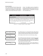
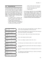
A
B
C
4–1
Remote Operation – 4
4
4
4
4
4
Remote Operation
Remote Operation
Remote Operation
Remote Operation
Remote Operation
4.1
Remote Operation ................................................................................ 4–1
4.2
Installation and Setup (IPScom
®
) ........................................................ 4–4
4.3
Operation ............................................................................................. 4–5
4.4
Checkout Status/Metering (Windows) .................................................4–16
4.5
Cautions ............................................................................................. 4–19
4.6
Keyboard Shortcuts ............................................................................4–20
4.7
IPSutil
™
Communications Software Package M-3890 .........................4–21
This chapter is designed for the person or group
responsible for the remote operation and setting of
the relay using the M-3820A IPScom
Communications Software package or other means.
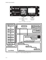
4.1
Remote Operation
The M-3425 Generator Protection Relay provides
three serial communication ports. Two serial
interface ports, COM1 and COM2, are standard 9-
pin, RS-232, DTE-configured ports. The front-panel
port, COM1, can be used to locally set and interrogate
the relay via a temporary connection to a PC or
laptop computer. The second RS-232 port, COM2,
is provided at the rear of the unit. Either port COM2
or COM3 may be used to remotely set and
interrogate the relay via a modem or other direct
serial connection. Equipment such as RTU’s, data
concentrators, modems, or computers can be
interfaced for direct, on-line, real time data
acquisition and control. Generally, all data available
to the operator through the front panel of the relay
with the optional M-3931 HMI module is accessible
remotely through the BECO 2200 or MODBUS data
exchange protocol. These protocol documents and
the database specific protocol document are
available from the factory or our website at
www.beckwithelectric.com.
The communication protocols implement serial, byte
oriented, asynchronous communication and can be
used to fulfill the following communications
functions:
•
Real-time monitoring of line status
•
Interrogation and modification of setpoints
•
Downloading of recorded oscillograph data
•
Reconfiguration of all relay functions
Direct Connection
In order for IPScom to communicate with the relay
via direct serial connection, a serial “null modem”
cable is required, with a 9-pin connector (DB9P) for
the system, and an applicable connector for the
computer (usually DB9S or DB25S). Pin-outs for a
null modem adapter are provided in Appendix B,
Communications.
An optional 10 foot null modem cable (M-0423) is
available from the factory, for direct connection
between a PC and the relay’s front panel COM port,
or the rear COM2 port.
Summary of Contents for M-3425
Page 1: ...Instruction Book M 3425 Generator Protection ...
Page 14: ... 13 M 3425 Generator Protection Relay Figure 1 External Connections ...
Page 33: ...x M 3425 Instruction Book This Page Left Intentionally Blank ...
Page 89: ...M 3425 Instruction Book 2 52 This Page Left Intentionally Blank ...
Page 125: ...1 3 A B C M 3425 Instruction Book 4 26 This Page Left Intentionally Blank ...
Page 187: ...M 3425 Instruction Book 6 50 This Page Left Intentionally Blank ...
Page 207: ...M 3425 Instruction Book C 4 This Page Left Intentionally Blank ...
Page 209: ...D 2 M 3425 Instruction Book Figure D 1 Volts Hz 24 Inverse Curve Family 1 Inverse Square ...
Page 210: ...Inverse Time Curves Appendix D D 3 Figure D 2 Volts Hz 24 Inverse Family Curve 2 ...
Page 211: ...D 4 M 3425 Instruction Book Figure D 3 Volts Hz 24IT Inverse Curve Family 3 ...
Page 212: ...Inverse Time Curves Appendix D D 5 Figure D 4 Volts Hz 24IT Inverse Curve Family 4 ...
Page 215: ...D 8 M 3425 Instruction Book Figure D 5 Definite Time Overcurrent Curve ...
Page 216: ...Inverse Time Curves Appendix D D 9 Figure D 6 Inverse Time Overcurrent Curve ...
Page 217: ...D 10 M 3425 Instruction Book Figure D 7 Very Inverse Time Overcurrent Curve ...
Page 218: ...Inverse Time Curves Appendix D D 11 Figure D 8 Extremely Inverse Time Overcurrent Curve ...
Page 223: ...D 16 M 3425 Instruction Book This Page Intentionally Left Blank ...


