


M-3425 Instruction Book
6–42
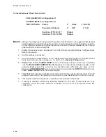
64B Brush Lift-Off Detection
VOLTAGE INPUTS:None
CURRENT INPUTS:None
TEST SETTINGS:
Pickup
P
mV
(0 to 5000)
Time Delay
D
Cycles
(1 to 8160)
Injection Frequency
IF
Hz
(0.10 to 1.00)
Programmed Outputs
Z
OUT
(1 to 8)
Function 64F
Disable
1.
Disable functions as shown. See Section 3.2, Initial Setup Procedure/Settings, Configure Relay
Data, for procedure.
2.
Confirm settings to be tested.
3.
Connect M-3921 Field Ground Coupler and decade box as shown in Figure 6-14, set Rf to open
(infinity) and Cf to 1
µ
f.
4.
Monitor the FIELD GND MEAS. CIRCUIT display under the VOLTAGE menu in MONITOR
STATUS. Set the pickup (P) to 110% of the displayed value.
5.
Pickup Test: Hold the TARGET RESET button in and open Cf and the FIELD GND/BRUSH LIFT
64F/B LED or the pickup indicator on the IPScom
®
Function Status screen will illuminate.
Connect the capacitor Cf before starting the timing test. Press the TARGET RESET button again
to remove targets.
6.
Time Test: With output contact (Z) connected to stop the timer, remove the capacitance
connected to the decade box and start timing. The operating time will be after D cycles, within ±(2/
IF + 1) sec.
7.
If testing is complete, enable any functions disabled for this test. If other tests are to be
completed, check the proper functions to disable for the next test and proceed from this
configuration.
Summary of Contents for M-3425
Page 1: ...Instruction Book M 3425 Generator Protection ...
Page 14: ... 13 M 3425 Generator Protection Relay Figure 1 External Connections ...
Page 33: ...x M 3425 Instruction Book This Page Left Intentionally Blank ...
Page 89: ...M 3425 Instruction Book 2 52 This Page Left Intentionally Blank ...
Page 125: ...1 3 A B C M 3425 Instruction Book 4 26 This Page Left Intentionally Blank ...
Page 187: ...M 3425 Instruction Book 6 50 This Page Left Intentionally Blank ...
Page 207: ...M 3425 Instruction Book C 4 This Page Left Intentionally Blank ...
Page 209: ...D 2 M 3425 Instruction Book Figure D 1 Volts Hz 24 Inverse Curve Family 1 Inverse Square ...
Page 210: ...Inverse Time Curves Appendix D D 3 Figure D 2 Volts Hz 24 Inverse Family Curve 2 ...
Page 211: ...D 4 M 3425 Instruction Book Figure D 3 Volts Hz 24IT Inverse Curve Family 3 ...
Page 212: ...Inverse Time Curves Appendix D D 5 Figure D 4 Volts Hz 24IT Inverse Curve Family 4 ...
Page 215: ...D 8 M 3425 Instruction Book Figure D 5 Definite Time Overcurrent Curve ...
Page 216: ...Inverse Time Curves Appendix D D 9 Figure D 6 Inverse Time Overcurrent Curve ...
Page 217: ...D 10 M 3425 Instruction Book Figure D 7 Very Inverse Time Overcurrent Curve ...
Page 218: ...Inverse Time Curves Appendix D D 11 Figure D 8 Extremely Inverse Time Overcurrent Curve ...
Page 223: ...D 16 M 3425 Instruction Book This Page Intentionally Left Blank ...


