


M-3425 Instruction Book
6–10
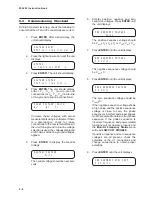
1.
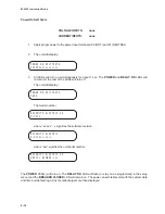
When DISPLAY TEST is displayed,
press the right arrow button until the
following is displayed:
COM1 LOOPBACK TEST
"
COM1 com2 com3 clock
!
2.
Press ENTER. The following is displayed:
COM1 LOOPBACK TEST
CONNECT LOOPBACK PLUG
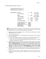
3.
Connect the loop-back plug to COM1,
the front-panel RS-232C connector.
4.
Press ENTER. After the test, the
following is displayed:
COM1 LOOPBACK TEST
-DONE-
5.
Press EXIT to return to the DIAGNOSTIC
MODE menu.
6.
When COM1 TEST is displayed, press
the right arrow button until COM2 TEST
appears and repeat steps 1 through 5 for
COM2. Continue to COM3 TEST.
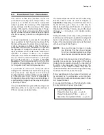
COM3 Test (2-Wire)
The COM3 Echo Test 2-Wire allows the user to test
the RS-485 rear terminal connections for proper
operation.
■
■
■
■
■
NOTE: This test requires a PC with an RS-485
converter and terminal emulator software
installed.
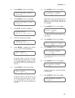
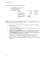
1.
When COM2 LOOPBACK TEST is
displayed, press the right arrow button
until the following is displayed:
COM3 ECHO TEST 2 WIRE
"
com1 com2 COM3 clock
!
2.
Press ENTER. The following is displayed:
COM3 ECHO TEST 2WIRE
IDLING...9600, N, 8, 1
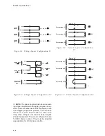
3.
On the rear of the unit, connect a PC to
the relay at terminals 3(-) and 4(+) via
RS-485 converter set for 2-wire operation.
See Figure 6-10 for diagram.
-
+
3
4
Computer
RS-232 to RS-485
converter or PC card
(2 wire)
RS-485
COM3
+
-
RS-485
RS-232
Figure 6-10
RS-485 2-Wire Testing
4.
Set the following PC communications
parameters:
Baud Rate
9600
Parity
None
Data Bits
8
Stop Bits
1
Duplex
Half
5.
Open the terminal emulator program on
the PC and open the COM port for the
RS-485 converter.
6.
Press a key on the PC keyboard. Verify
that the character pressed shows
temporarily on the relay’s display, and
appears on the PC monitor.
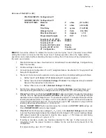
7.
When communication has been verified,
press EXIT. The following is displayed:
COM3 ECHO TEST 2WIRE
-DONE-
Summary of Contents for M-3425
Page 1: ...Instruction Book M 3425 Generator Protection ...
Page 14: ... 13 M 3425 Generator Protection Relay Figure 1 External Connections ...
Page 33: ...x M 3425 Instruction Book This Page Left Intentionally Blank ...
Page 89: ...M 3425 Instruction Book 2 52 This Page Left Intentionally Blank ...
Page 125: ...1 3 A B C M 3425 Instruction Book 4 26 This Page Left Intentionally Blank ...
Page 187: ...M 3425 Instruction Book 6 50 This Page Left Intentionally Blank ...
Page 207: ...M 3425 Instruction Book C 4 This Page Left Intentionally Blank ...
Page 209: ...D 2 M 3425 Instruction Book Figure D 1 Volts Hz 24 Inverse Curve Family 1 Inverse Square ...
Page 210: ...Inverse Time Curves Appendix D D 3 Figure D 2 Volts Hz 24 Inverse Family Curve 2 ...
Page 211: ...D 4 M 3425 Instruction Book Figure D 3 Volts Hz 24IT Inverse Curve Family 3 ...
Page 212: ...Inverse Time Curves Appendix D D 5 Figure D 4 Volts Hz 24IT Inverse Curve Family 4 ...
Page 215: ...D 8 M 3425 Instruction Book Figure D 5 Definite Time Overcurrent Curve ...
Page 216: ...Inverse Time Curves Appendix D D 9 Figure D 6 Inverse Time Overcurrent Curve ...
Page 217: ...D 10 M 3425 Instruction Book Figure D 7 Very Inverse Time Overcurrent Curve ...
Page 218: ...Inverse Time Curves Appendix D D 11 Figure D 8 Extremely Inverse Time Overcurrent Curve ...
Page 223: ...D 16 M 3425 Instruction Book This Page Intentionally Left Blank ...


