


M-3425 Instruction Book
2–26
Phase Initiate Enable
IN1 (52b)
Logic high when breaker closed
AND
NOT
OR
50BF-Ph
Overcurrent
I>P.U.
Output Initiate
Input Initiate
OR
50BF-N
Overcurrent
I>P.U.
Neutral Initiate Enable
AND
DELAY
TIME
Programmed
Output
Contacts
AND
Logic high
when breaker open
Figure 2-12
Breaker Failure Logic Diagram
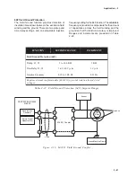
50BF Generator Breaker Failure/HV Breaker
Flashover
The 50BF function is applicable when a generator
breaker is present and line side generator CTs are
being used. The 50BF-Ph phase detector element
(if enabled) is used for breaker failure and the
50BF-N (if enabled) provides breaker flashover
protection by providing an additional breaker failure
initiate which is only active when the breaker is
open. For high impedance grounded applications,
the 50BF-N function is inapplicable and must be
disabled. Ranges and increments are presented in
Table 2-10, Breaker Failure (50BF) Setpoint Ranges.
50BF-Ph Generator Breaker Failure: When the
M-3425 Generator Protection Relay detects an
internal fault or an abnormal operating condition, it
closes an output contact to trip the generator breaker
or the unit HV breaker. When a generator breaker is
used, protection is available for the instance where
it fails to clear the fault or abnormal condition. Such
generator breaker failure protection output contacts
must be connected to trip the additional necessary
breakers to isolate the generator from the system.
The breaker-failure condition is usually detected by
the continued presence of current in any one or
more of the phases after a breaker has been tripped.
However, the current detector (50BF-Ph) may not
always give the correct status of the breaker,
especially for generator breakers. This is because
faults and abnormal operating conditions such as
ground faults, overexcitation, over/under frequency,
and reverse power may not produce enough current
to operate the current detectors. For this reason,
the breaker status input 52b contact must be used,
in addition to the 50BF-Ph, to provide adequate
breaker status indication.
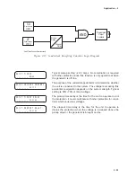
Implementation of the generator breaker failure
function is illustrated in Figure 2-13. The breaker
failure timer will be started whenever any one of the
designated output contacts or the external
programmed breaker failure initiate status input are
operated. The timer continues to time if any one of
the phase currents are above the 50BF-Ph pickup
setting or if the 52b contact indicates the breaker is
still closed; otherwise, the timer is reset.
Since current in the generator high side CT which
energizes the 50BF protection (I
A
, I
B
, I
C
) might not
extinguish concurrently with the breaker opening for
faults between the CT location and the generator
breaker, a possible area of mis-operation exists.
Usually the risk of faults in this limited area is small
enough to be ignored but should be considered.
50BF-Neutral Element: This instantaneous
overcurrent relay is energized from the generator
neutral CT (See Figure 2-1, One-Line Functional
Diagram). This function is internally in series with a
breaker “b” contact (IN1) to provide logic for the
breaker flashover protection (see Figure 2-13).
HV Breaker Failure (limited) The breaker failure
function may be used for a unit breaker rather than
a generator breaker. It is limited in that it has no
fault detector associated with the unit breaker. Output
contact operation would occur if any of the initiate
contacts close and the 52b contact indicated a
closed breaker after the set time delay.
This operation is chosen by disabling the neutral
element, disabling the phase element, and
designating initiating inputs and outputs and a time
delay setting.
Summary of Contents for M-3425
Page 1: ...Instruction Book M 3425 Generator Protection ...
Page 14: ... 13 M 3425 Generator Protection Relay Figure 1 External Connections ...
Page 33: ...x M 3425 Instruction Book This Page Left Intentionally Blank ...
Page 89: ...M 3425 Instruction Book 2 52 This Page Left Intentionally Blank ...
Page 125: ...1 3 A B C M 3425 Instruction Book 4 26 This Page Left Intentionally Blank ...
Page 187: ...M 3425 Instruction Book 6 50 This Page Left Intentionally Blank ...
Page 207: ...M 3425 Instruction Book C 4 This Page Left Intentionally Blank ...
Page 209: ...D 2 M 3425 Instruction Book Figure D 1 Volts Hz 24 Inverse Curve Family 1 Inverse Square ...
Page 210: ...Inverse Time Curves Appendix D D 3 Figure D 2 Volts Hz 24 Inverse Family Curve 2 ...
Page 211: ...D 4 M 3425 Instruction Book Figure D 3 Volts Hz 24IT Inverse Curve Family 3 ...
Page 212: ...Inverse Time Curves Appendix D D 5 Figure D 4 Volts Hz 24IT Inverse Curve Family 4 ...
Page 215: ...D 8 M 3425 Instruction Book Figure D 5 Definite Time Overcurrent Curve ...
Page 216: ...Inverse Time Curves Appendix D D 9 Figure D 6 Inverse Time Overcurrent Curve ...
Page 217: ...D 10 M 3425 Instruction Book Figure D 7 Very Inverse Time Overcurrent Curve ...
Page 218: ...Inverse Time Curves Appendix D D 11 Figure D 8 Extremely Inverse Time Overcurrent Curve ...
Page 223: ...D 16 M 3425 Instruction Book This Page Intentionally Left Blank ...


