


M-3425 Instruction Book
6–2
6.1
Equipment/Test Setup
No calibration is necessary, as the M-3425
Generator Protection Relay is calibrated and fully
tested at the factory. If calibration is necessary
because of a component replacement, follow the
auto calibration procedure detailed in Section 6.3,
Auto Calibration (or see Section 5.4 for units without
an HMI). These test procedures are based on the
prerequisite that the functions are enabled and have
settings as described in Chapter 2, Application,
and that the unit is fitted with the optional HMI
module.
Equipment Required
The following equipment is required to carry out the
test procedures:
1.
Two Digital Multimeters (DMM) with 10
A current range.
2.
120 V ac or 0 to 125 V dc variable
supply for system power.
3.
Three-phase independent voltage sources
(0 to 250 V) variable phase to simulate
VT inputs.
4.
Three-phase independent current sources
(0 to 25 A) variable phase to simulate
CT inputs.
5.
Electronic timer accurate to at least 8
ms.
6.
For relays with the 64F/B option:
a.
Resistor decade box capable of
500 ohms to 150 kOhms, able to
step in 100 ohm increments.
b.
Capacitors ranging from 0.15 mf to
10
µ
f.
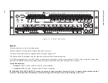
Setup
1.
Connect system power to the power input
terminals 62 (hot) and 63 (neutral). The
relay can be ordered with a nominal input
power supply of 110/120/230/240 Vac,
110/125/220/250 Vdc
or 24/48 Vdc. An
optional redundant power supply is
available.
■
■
■
■
■
NOTE: The proper voltage for the relay is clearly
marked on the power supply label affixed
to the rear panel.
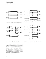
2.
For each test procedure, connect the
voltage and current sources according
to the configuration listed in the test
procedure and follow the steps outlined.
When the testing of one function may
cause another function to operate
depending on the particular settings, it is
recommended the untested function be
disabled. (See Table 6-1.)
Summary of Contents for M-3425
Page 1: ...Instruction Book M 3425 Generator Protection ...
Page 14: ... 13 M 3425 Generator Protection Relay Figure 1 External Connections ...
Page 33: ...x M 3425 Instruction Book This Page Left Intentionally Blank ...
Page 89: ...M 3425 Instruction Book 2 52 This Page Left Intentionally Blank ...
Page 125: ...1 3 A B C M 3425 Instruction Book 4 26 This Page Left Intentionally Blank ...
Page 187: ...M 3425 Instruction Book 6 50 This Page Left Intentionally Blank ...
Page 207: ...M 3425 Instruction Book C 4 This Page Left Intentionally Blank ...
Page 209: ...D 2 M 3425 Instruction Book Figure D 1 Volts Hz 24 Inverse Curve Family 1 Inverse Square ...
Page 210: ...Inverse Time Curves Appendix D D 3 Figure D 2 Volts Hz 24 Inverse Family Curve 2 ...
Page 211: ...D 4 M 3425 Instruction Book Figure D 3 Volts Hz 24IT Inverse Curve Family 3 ...
Page 212: ...Inverse Time Curves Appendix D D 5 Figure D 4 Volts Hz 24IT Inverse Curve Family 4 ...
Page 215: ...D 8 M 3425 Instruction Book Figure D 5 Definite Time Overcurrent Curve ...
Page 216: ...Inverse Time Curves Appendix D D 9 Figure D 6 Inverse Time Overcurrent Curve ...
Page 217: ...D 10 M 3425 Instruction Book Figure D 7 Very Inverse Time Overcurrent Curve ...
Page 218: ...Inverse Time Curves Appendix D D 11 Figure D 8 Extremely Inverse Time Overcurrent Curve ...
Page 223: ...D 16 M 3425 Instruction Book This Page Intentionally Left Blank ...


