


6–9
Testing – 6
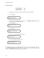
Display Test
The DISPLAY TEST menu selection enables the
user to check the display. This test cycles through
varying test patterns until EXIT is pressed.
1.
When BUTTON TEST is displayed, press
the right arrow button until the following
is displayed:
DISPLAY TEST
"
ex_io button DISP
!
2.
Press ENTER. The unit will display a
sequence of test characters until EXIT
is pushed.
3.
After the test has cycled through
completely, press EXIT to return to the
DIAGNOSTIC MODE menu.
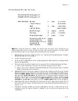
COM1/COM2/COM3 Loopback Test
The COM1 LOOPBACK TEST menu allows the
user to check the front-panel RS-232C port. A loop-
back plug is required for this test. COM2
LOOPBACK TEST menu checks the rear panel
RS-232C port.
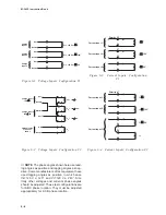
M-3425
COM1/COM2
DB9P
1
RX
2
TX
3
4
SGND
5
6
RTS
7
CTS
8
9
Figure 6-9
COM1/COM2 Loopback Plug
■
■
■
■
■
NOTE: The loopback plug required consists of a
DB9P connector (male) with pin 2 (RX)
connected to pin 3 (TX) and pin 7 (RTS)
connected to pin 8 (CTS). No other
connections are necessary.
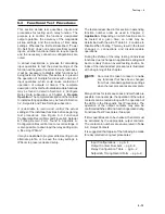
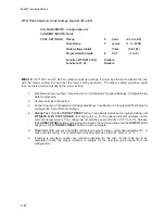
Button Test
The BUTTON TEST menu selection allows the
user to check the M-3931 HMI Module buttons. As
each button is pressed, its name is displayed.
BECKWITH ELECTRIC CO.
M-3425
EXIT
ENTER
a
a
a
a
Figure 6-8
M-3931 Human-Machine
Interface Module
1.
When the TARGET LED TEST is
displayed, press the right arrow button
until the following is displayed:
BUTTON TEST
"
ex_io BUTTON disp
!
2.
Press ENTER. The following is
displayed:
BUTTON TEST
0
3.
Press each button for test. As each
button is pressed, the display will briefly
show the name for each key (“RIGHT
ARROW”, “UP ARROW”, etc).
■
NOTE: Pressing the EXIT button will exit from
this test, so it should be tested last. If it
is pushed before this test sequence is
completed, the test may be restarted by
pushing ENTER. Notice that the word
EXIT is displayed temporarily before the
test sequence is exited.
Summary of Contents for M-3425
Page 1: ...Instruction Book M 3425 Generator Protection ...
Page 14: ... 13 M 3425 Generator Protection Relay Figure 1 External Connections ...
Page 33: ...x M 3425 Instruction Book This Page Left Intentionally Blank ...
Page 89: ...M 3425 Instruction Book 2 52 This Page Left Intentionally Blank ...
Page 125: ...1 3 A B C M 3425 Instruction Book 4 26 This Page Left Intentionally Blank ...
Page 187: ...M 3425 Instruction Book 6 50 This Page Left Intentionally Blank ...
Page 207: ...M 3425 Instruction Book C 4 This Page Left Intentionally Blank ...
Page 209: ...D 2 M 3425 Instruction Book Figure D 1 Volts Hz 24 Inverse Curve Family 1 Inverse Square ...
Page 210: ...Inverse Time Curves Appendix D D 3 Figure D 2 Volts Hz 24 Inverse Family Curve 2 ...
Page 211: ...D 4 M 3425 Instruction Book Figure D 3 Volts Hz 24IT Inverse Curve Family 3 ...
Page 212: ...Inverse Time Curves Appendix D D 5 Figure D 4 Volts Hz 24IT Inverse Curve Family 4 ...
Page 215: ...D 8 M 3425 Instruction Book Figure D 5 Definite Time Overcurrent Curve ...
Page 216: ...Inverse Time Curves Appendix D D 9 Figure D 6 Inverse Time Overcurrent Curve ...
Page 217: ...D 10 M 3425 Instruction Book Figure D 7 Very Inverse Time Overcurrent Curve ...
Page 218: ...Inverse Time Curves Appendix D D 11 Figure D 8 Extremely Inverse Time Overcurrent Curve ...
Page 223: ...D 16 M 3425 Instruction Book This Page Intentionally Left Blank ...


