


6–11
Testing – 6
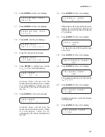
8.
Close the COM port on the PC, and exit
the terminal program.
Clock Test
CLOCK TEST
"
com1 com2 com3 CLOCK
!
1.
Press ENTER for the unit to display:
CLOCK TEST
01-Jan-2001 01:01:80
2.
Pressing ENTER will start the clock for
testing, and unit will display:
CLOCK TEST
CLOCK START
3.
Repeat number 2 above to stop clock.
4.
When finished, press EXIT twice. After
initial press of EXIT, unit will display:
CLOCK TEST
-DONE-
■
■
■
■
■
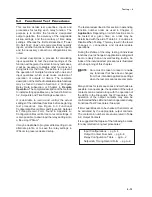
NOTE: ‘80’ will be displayed in the seconds
place when the clock is stopped. To
preserve battery life, the clock should
be stopped if the unit is to be powered
down for long periods of time.
Flash Relay OK LED Test
1.
Press the right arrow until the unit
displays:
FLASH RELAY OK LED
"
clock LED cal factory
2.
Press ENTER. Unit will display:
FLASH RELAY OK LED
OFF on
3.
Use the right arrow key to select “ON”,
and press Enter. The unit will display
FLASH RELAY OK LED
-DONE-
4.
Press Exit to return to the former menu.
Auto Calibration
Refer to the following Section 6.3, Auto Calibration,
for more information on that function.
AUTO CALIBRATION
"
clock led CAL factory
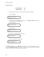
Factory Use Only
This function is provided to allow access by factory
personnel.
FACTORY USE ONLY
"
clock led cal FACTORY
6.3
Auto Calibration
■
■
■
■
■
NOTE: The M-3425 Generator Protection Relay
has been fully calibrated at the factory.
There is no need to recalibrate the unit
prior to initial installation (In-system
calibration of the 64F function may be
needed for units purchased with the 64F
Field Ground option). Calibration can be
initiated via the HMI or IPSutil™ program.
Phase and Neutral Fundamental Calibration
1.
Enter Diagnostic Mode and press the
right arrow button until the following is
displayed:
AUTO CALIBRATION
"
CAL factory
2.
Press ENTER. The following is displayed:
CONNECT REFERENCE INPUTS
PRESS ENTER TO CALIBRATE
Summary of Contents for M-3425
Page 1: ...Instruction Book M 3425 Generator Protection ...
Page 14: ... 13 M 3425 Generator Protection Relay Figure 1 External Connections ...
Page 33: ...x M 3425 Instruction Book This Page Left Intentionally Blank ...
Page 89: ...M 3425 Instruction Book 2 52 This Page Left Intentionally Blank ...
Page 125: ...1 3 A B C M 3425 Instruction Book 4 26 This Page Left Intentionally Blank ...
Page 187: ...M 3425 Instruction Book 6 50 This Page Left Intentionally Blank ...
Page 207: ...M 3425 Instruction Book C 4 This Page Left Intentionally Blank ...
Page 209: ...D 2 M 3425 Instruction Book Figure D 1 Volts Hz 24 Inverse Curve Family 1 Inverse Square ...
Page 210: ...Inverse Time Curves Appendix D D 3 Figure D 2 Volts Hz 24 Inverse Family Curve 2 ...
Page 211: ...D 4 M 3425 Instruction Book Figure D 3 Volts Hz 24IT Inverse Curve Family 3 ...
Page 212: ...Inverse Time Curves Appendix D D 5 Figure D 4 Volts Hz 24IT Inverse Curve Family 4 ...
Page 215: ...D 8 M 3425 Instruction Book Figure D 5 Definite Time Overcurrent Curve ...
Page 216: ...Inverse Time Curves Appendix D D 9 Figure D 6 Inverse Time Overcurrent Curve ...
Page 217: ...D 10 M 3425 Instruction Book Figure D 7 Very Inverse Time Overcurrent Curve ...
Page 218: ...Inverse Time Curves Appendix D D 11 Figure D 8 Extremely Inverse Time Overcurrent Curve ...
Page 223: ...D 16 M 3425 Instruction Book This Page Intentionally Left Blank ...


