


6–43
Testing – 6
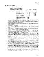
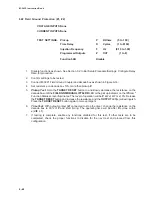
78 Out of Step
VOLTAGE INPUTS:Configuration V1
CURRENT INPUTS:Configuration C1
TEST SETTINGS:
Diameter
P
ohms
(0.1 to 100)
Offset
O
ohms
(–100 to +100)
Impedance Angle
A
Degrees
(0 to 90)
Time Delay
D
cycles
(1 to 8160)
Blinder Impedance
B
ohms
(0.1 to 50.0)
Trip on MHO Exit
See Below
Programmed Output
Z
Delta-Y Transform
Disable
Functions 21, 27, 27TN
Disable
Functions 32, 40, 51V
Disable
Functions 81, 87
Disable
■
■
■
■
■
NOTE: Use Figure 2-18 for reference. A stopwatch is required for this test.
1.
Disable functions as shown. See Section 3.2, Initial Setup Procedure/Settings, Configure Relay
Data, for procedure.
2.
Confirm settings to be tested.
3.
Connect inputs in Configuration V1 and C1 designated above. See Section 6.1, Equipment/Test
Setup for configurations. Adjust voltage and currents while monitoring the positive sequence
impedance to a point similar to point Z
0
in Figure 2-17.
4.
Pickup Test: Disable the TRIP ON MHO EXIT setting and set the delay, D, to a minimal setting.
Press and hold the TARGET RESET button and sweep the current angle towards point Z
1
. When
the impedance passes through point Z
1
, verify that the 78 OUT OF STEP LED comes on or the
function status indicator shows the function picked up on the Monitor Function Status screen.
Pause testing until the delay timer has time to expire. Continue to sweep the current angle to
point Z
2
, and verify output Z operates as point Z
2
is crossed, and resets after the seal-in time
delay.
Blocking on Stable Swing Test: Reset impedance to a point outside of the mho circle. Adjust
voltages and currents to point Z
0
. Press and hold the TARGET RESET button and sweep past
point Z
1
. Verify the 78 OUT OF STEP LED comes on or the function status indicator shows the
function picked up on the Monitor Function Status screen. Pause testing until the delay timer
has time to expire. Reverse sweep direction and sweep the current angle to point Z
1
, and verify
output Z does not operate and the 78 OUT OF STEP LED goes out or the function status
indicator shows the function reset on the Monitor Function Status screen as point Z
1
is
crossed.
5.
Pickup Test (Trip on mho Exit): Enable the TRIP ON MHO EXIT setting. Adjust voltages and
currents to point Z
0
. Press and hold the TARGET RESET button, and sweep the current angle
towards point Z
1
. When the impedance passes through point Z
1
, verify that the 78 OUT OF STEP
LED comes on or the function status indicator shows that the function has picked up on the
Monitor Function Status screen. Pause testing until the delay timer has time to expire.
Continue to sweep the current angle to point Z
2
, and verify that output Z does not operate as point
Z
2
is crossed. Sweep the impedance further towards point Z
3
, and verify output Z operates as
point Z
3
is crossed, and resets after the seal-in time delay.
Summary of Contents for M-3425
Page 1: ...Instruction Book M 3425 Generator Protection ...
Page 14: ... 13 M 3425 Generator Protection Relay Figure 1 External Connections ...
Page 33: ...x M 3425 Instruction Book This Page Left Intentionally Blank ...
Page 89: ...M 3425 Instruction Book 2 52 This Page Left Intentionally Blank ...
Page 125: ...1 3 A B C M 3425 Instruction Book 4 26 This Page Left Intentionally Blank ...
Page 187: ...M 3425 Instruction Book 6 50 This Page Left Intentionally Blank ...
Page 207: ...M 3425 Instruction Book C 4 This Page Left Intentionally Blank ...
Page 209: ...D 2 M 3425 Instruction Book Figure D 1 Volts Hz 24 Inverse Curve Family 1 Inverse Square ...
Page 210: ...Inverse Time Curves Appendix D D 3 Figure D 2 Volts Hz 24 Inverse Family Curve 2 ...
Page 211: ...D 4 M 3425 Instruction Book Figure D 3 Volts Hz 24IT Inverse Curve Family 3 ...
Page 212: ...Inverse Time Curves Appendix D D 5 Figure D 4 Volts Hz 24IT Inverse Curve Family 4 ...
Page 215: ...D 8 M 3425 Instruction Book Figure D 5 Definite Time Overcurrent Curve ...
Page 216: ...Inverse Time Curves Appendix D D 9 Figure D 6 Inverse Time Overcurrent Curve ...
Page 217: ...D 10 M 3425 Instruction Book Figure D 7 Very Inverse Time Overcurrent Curve ...
Page 218: ...Inverse Time Curves Appendix D D 11 Figure D 8 Extremely Inverse Time Overcurrent Curve ...
Page 223: ...D 16 M 3425 Instruction Book This Page Intentionally Left Blank ...


