


M-3425 Instruction Book
2–48
87GD Ground (Zero Sequence) Differential
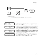
The Zero Sequence Differential function (87GD)
provides ground fault protection for low impedance
grounded generator applications. High sensitivity
and fast operation can be obtained using this
function. Ranges and increments are presented in
Table 2-27.
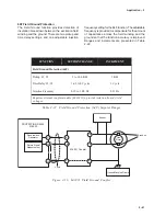
The relay provides a CT Ratio Correction Factor
(R
C
) which removes the need for auxiliary CTs when
the phase and neutral CT ratios are different.
When the system can supply zero sequence current
to the ground fault (such as when several generators
are bussed together), the 87GD function operates
directionally. The directional element calculates the
product (–3I
0
I
N
CosØ) for directional indication. The
relay will operate only if I
0
(Zero sequence current
derived from phase CTs) and I
N
(Neutral current
from Neutral CT) have the opposite polarity, which
is the case for internal generator faults.
The advantage of directional sensitivity is the security
against ratio errors and CT saturation during faults
external to the protected generator.
The directional element is inoperative if the residual
current (3I
0
) is approximately less than 0.2 A, in
which case the algorithm automatically disables the
directional element and the 87GD function becomes
non-directional differential. The pickup quantity is
then calculated as the difference between the
corrected triple zero-sequence current (R
C
3I
0
) and
the neutral current (I
N
). The magnitude of the
difference x(R
C
3I
0
–I
N
)x is compared to the relay
pickup.
For security purposes during external high phase-
fault current causing CT saturation, this function is
disabled any time the value of I
N
is less than
approximately 0.20 amps.
N
O
I
T
C
N
U
F
E
G
N
A
R
T
N
I
O
P
T
E
S
T
N
E
M
E
R
C
N
I
)
D
G
7
8
(
l
a
i
t
n
e
r
e
f
f
i
D
d
n
u
o
r
G
p
u
k
c
i
P
A
0
0
.
0
1
o
t
0
2
.
0
)
A
0
0
.
2
o
t
4
0
.
0
(
1
0
.
0
y
a
l
e
D
e
m
i
T
s
e
l
c
y
C
0
6
1
8
o
t
1
e
l
c
y
C
1
R
(
n
o
i
t
c
e
r
r
o
C
o
i
t
a
R
T
C
C
)
9
9
.
7
o
t
0
1
.
0
1
0
.
0
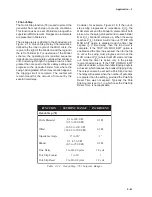
Table 2-27
Ground Differential (87GD) Setpoint Ranges
A typical setting is 0.2 amps. (Relay amps = primary amps ÷ CT
ratio.) For higher values of R
C
, noise may create substantial differential
current making higher pickup settings desirable.
In order to prevent mis-operation during external faults with CT
saturation conditions, a time delay of 6 cycles or higher is
recommended.
CT Ratio Correction Factor = (Phase CT Ratio)/(Neutral CT Ratio)
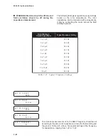
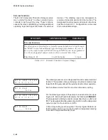
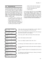
87GD PICKUP
________ Amps
87GD DELAY
________ Cycles
87GD C.T. RATIO CORRECT
________
Summary of Contents for M-3425
Page 1: ...Instruction Book M 3425 Generator Protection ...
Page 14: ... 13 M 3425 Generator Protection Relay Figure 1 External Connections ...
Page 33: ...x M 3425 Instruction Book This Page Left Intentionally Blank ...
Page 89: ...M 3425 Instruction Book 2 52 This Page Left Intentionally Blank ...
Page 125: ...1 3 A B C M 3425 Instruction Book 4 26 This Page Left Intentionally Blank ...
Page 187: ...M 3425 Instruction Book 6 50 This Page Left Intentionally Blank ...
Page 207: ...M 3425 Instruction Book C 4 This Page Left Intentionally Blank ...
Page 209: ...D 2 M 3425 Instruction Book Figure D 1 Volts Hz 24 Inverse Curve Family 1 Inverse Square ...
Page 210: ...Inverse Time Curves Appendix D D 3 Figure D 2 Volts Hz 24 Inverse Family Curve 2 ...
Page 211: ...D 4 M 3425 Instruction Book Figure D 3 Volts Hz 24IT Inverse Curve Family 3 ...
Page 212: ...Inverse Time Curves Appendix D D 5 Figure D 4 Volts Hz 24IT Inverse Curve Family 4 ...
Page 215: ...D 8 M 3425 Instruction Book Figure D 5 Definite Time Overcurrent Curve ...
Page 216: ...Inverse Time Curves Appendix D D 9 Figure D 6 Inverse Time Overcurrent Curve ...
Page 217: ...D 10 M 3425 Instruction Book Figure D 7 Very Inverse Time Overcurrent Curve ...
Page 218: ...Inverse Time Curves Appendix D D 11 Figure D 8 Extremely Inverse Time Overcurrent Curve ...
Page 223: ...D 16 M 3425 Instruction Book This Page Intentionally Left Blank ...


