


1
3
A
B
C
4–23
Remote Operation – 4
Clock Command
Comm
Relay Comm
Clock
Security
Miscellaneous Help
IPSutility
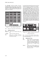
When the Clock command is selected, the “Set
Unit Date/Time” dialog box appears (See Figure
4-26). Date and Time can be changed and sent to
the relay. This dialog box allows you to start or stop
the clock in the relay.
Security Menu
Security
Change Level Access Code
Change Comm Access Code
The Security Menu allows you to set the
communication access code and the level access
codes for the relay.
The Change Comm Access Code allows you to
assign new communication access code to the
relay. The range of the access code is 1 to 9999.
Note that the access code 9999 is a factory default
(See Figure 4-27).
■
■
■
■
■
NOTE: Setting the access code to 9999 disables
security.
The Change User Access Code allows you to
assign three different levels of access code for the
relay functions accessibility. The range of the level
access code is 1 to 9999 (See Figure 4-28).
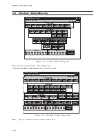
Miscellaneous Menu
Miscellaneous
Setup
Monitor Status
Calibration
Advanced
The Miscellaneous menu allows you to set and
monitor some of the relay parameters.
The Setup command allows you to change the
users Logo information, test outputs, assign
communication address and user control number,
phase rotation, OK LED flash mode in the relay.
Note that the highest number used for the
communication address is 255 and the highest
control number allowed is 9999 (See Figure 4-29).
The Monitor Status command allows you to monitor
and clear the error code counters, monitor the check
sums, and to view inputs test status. Note that the
powerloss counter cannot be cleared.
The Calibration command allows easy access to
the relay’s Autocalibration features (see also Section
6.3, Autocalibration), including Auto Calibrate,
Nominal Frequency, Third Harmonic, and, if
purchased, the 64F Field Ground function. See
Figure 4-23, below.
The Advanced command is reserved for factory
use only.
Select Calibration
Procedures
Connect VA=VB=VC=VN=12.0 (+/- 0.01)
VAC at 50 Hz, 0 deg phase and
Ia=Ib=Ic=IA=IB=IC=IN=5.00 (+/- 0.01) A at 0
deg phase. Press Calibrate when ready.
Nominal Frequency
Third Harmonic
64F Field Ground
64S Stator Protection
Calibrate
Cancel
X
Calibration
Figure 4-23
Calibration Dialog Box
Summary of Contents for M-3425
Page 1: ...Instruction Book M 3425 Generator Protection ...
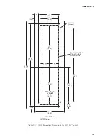
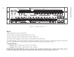
Page 14: ... 13 M 3425 Generator Protection Relay Figure 1 External Connections ...
Page 33: ...x M 3425 Instruction Book This Page Left Intentionally Blank ...
Page 89: ...M 3425 Instruction Book 2 52 This Page Left Intentionally Blank ...
Page 125: ...1 3 A B C M 3425 Instruction Book 4 26 This Page Left Intentionally Blank ...
Page 187: ...M 3425 Instruction Book 6 50 This Page Left Intentionally Blank ...
Page 207: ...M 3425 Instruction Book C 4 This Page Left Intentionally Blank ...
Page 209: ...D 2 M 3425 Instruction Book Figure D 1 Volts Hz 24 Inverse Curve Family 1 Inverse Square ...
Page 210: ...Inverse Time Curves Appendix D D 3 Figure D 2 Volts Hz 24 Inverse Family Curve 2 ...
Page 211: ...D 4 M 3425 Instruction Book Figure D 3 Volts Hz 24IT Inverse Curve Family 3 ...
Page 212: ...Inverse Time Curves Appendix D D 5 Figure D 4 Volts Hz 24IT Inverse Curve Family 4 ...
Page 215: ...D 8 M 3425 Instruction Book Figure D 5 Definite Time Overcurrent Curve ...
Page 216: ...Inverse Time Curves Appendix D D 9 Figure D 6 Inverse Time Overcurrent Curve ...
Page 217: ...D 10 M 3425 Instruction Book Figure D 7 Very Inverse Time Overcurrent Curve ...
Page 218: ...Inverse Time Curves Appendix D D 11 Figure D 8 Extremely Inverse Time Overcurrent Curve ...
Page 223: ...D 16 M 3425 Instruction Book This Page Intentionally Left Blank ...


