Service Manual
Green Bedding Separator eng_deu June 2012
Page 33 of 43
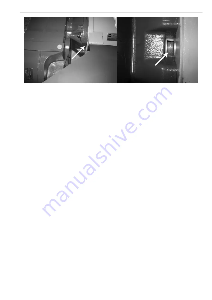
Figure 5.1:
Inspection of the Checking Tap for securing the function of the Stoppage Sealing
Abb. 5.1:
Begutachtung der Kontrollöffnung zur Sicherung der Funktionstüchtigkeit der
Sperrdichtung
Access to replace the seals in the stoppage sealing
package is achieved by the following steps:
1. Remove the auger with the endplate by
loosening the auger bolt at the end of the auger.
2. Remove the top of the inlet assembly by
removing the 12 nuts to allow free access to the
hub and the cover plate, then remove the four
resp. eight nuts to remove the parallel shaft
helical geared motor .
3. Unscrew four long and two short bolts from the
seal holder.
4. Use two of the four long bolts in the threaded
holes of the two short bolts to press the seal
holder out.
5. Take the cover plate off. Exchange the worn
sealing rings against new spare parts (1
Simmerring and 1 Cassette Ring). Cassette
Ring is secured by a circlip! Pay attention to the
working direction of the seals, also see drawing
in service manual for the parallel shaft helical
geared motor.
6. Attention: Do not lubricate the gearbox shaft!
The inliner of the Cassette must be mounted
dry, so that it can
not
rotate on the shaft!
Additionally, the lubricating hole in the seal
holder must match with the lubrication hole in
the flange
Note
: There is only one position for
the seal holder, which matches with all eight
screw holes.
7. Screw the cover plate on with the four short
bolts and the seal holder with the four long bolts
into the gearbox flange and fix all 8 screws.
Replace the paper seal if necessary!
8. Now reassemble the parallel shaft helical
geared motor and the inlet assembly.
9. Supply "stoppage medium" until the "stoppage
medium" squeezes out between the cover plate
and hub. The gear motor has to run with
"stoppage medium" to ensure that the whole
area in front of the sealing is filled.
10. Assemble the auger with the auger bolt.
Um die Dichtungen im Sperrdichtungspaket
auszutauschen, gehen Sie folgendermaßen vor:
1. Demontieren Sie die Schnecke mit der
Endplatte, indem Sie die Innenverstrebung der
Schnecke lösen.
2. Lösen Sie die zwölf Muttern am Einlaufkasten
um ungehinderten Zugang zur Nabe und
Schutzplatte zu erhalten, oder lösen Sie
alternativ die vier bzw. acht Muttern um den
Getriebemotor abzubauen.
3. Lösen Sie vier lange und 2 kurze Schrauben an
dem Dichtungsträger.
4. Verwenden Sie zwei der vier langen Schrauben
in den Gewindebohrungen der 2 kurzen und
drücken Sie mit diesen Schrauben den
Dichtungsträger aus dem Flansch.
5. Entfernen Sie die Abdeckplatte.Tauschen Sie
nun die verschlissenen Dichtungen (1 x
Simmerring und 1 x Kassettendichtring) im
Dichtungsträger gegen neue Dichtungen aus.
Der Kassettenring ist mit einem Sprengring
gesichert! Beachten Sie dabei die
Abdichtungsrichtung, siehe auch die Zeichnung
in der Bedienungsanleitung des
Getriebemotors.
6. Achtung: Getriebewelle nicht einfetten! Der
Innenring des Kassettendichtrings muß trocken
montiert werden, damit er sich
nicht
auf der
Welle drehen kann.Die Schmierbohrung muss
mit der Schmierbohrung des Flansches in
Deckung liegen. Hinweis: Es gibt nur eine
Position des Dichtungsträgers, in der alle acht
Schrauben montiert werden können.
7. Schrauben Sie mit den 4 kurzen Schrauben die
Abdeckplatte auf und mit den vier langen
Schrauben das Sperrdichtungspaket in den
Flanschsitz. Papierdichtung ggfs. erneuern!
Ziehen Sie alle 8 Schrauben reihum an.
8. Nun können der Getriebemotor, sofern dieser
abgebaut wurde und der Einlaufkasten wieder
montiert werden.
11.
Gear Box
Getriebe
Inlet housing
Einlaufgehäuse
Frame
Gestell
Checking Tap
Kontrollöffnung
Checking Tap
Kontrollöffnung


