


19. Board Diagnostic LED’s
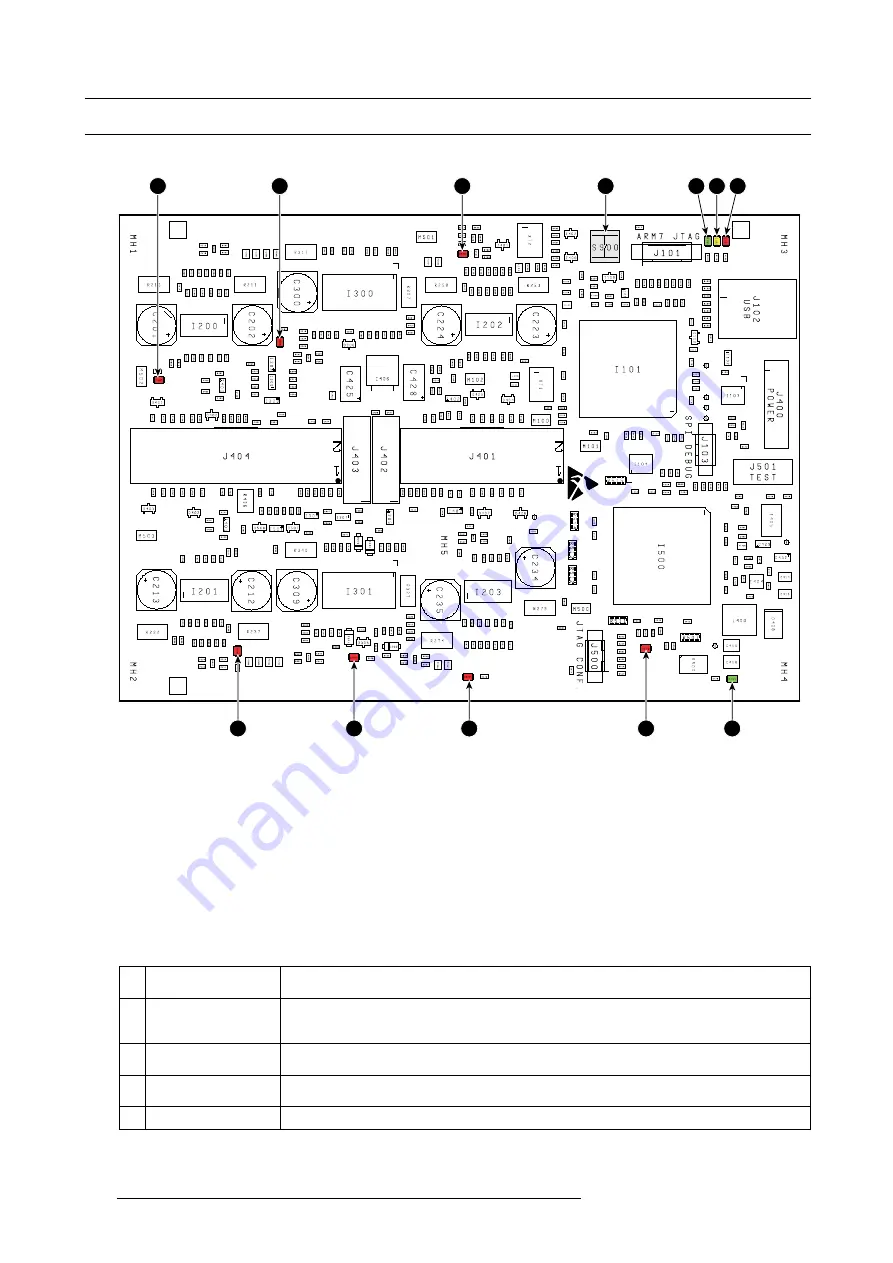
19.2 Motor Control Board Diagnostic LEDs
Location of the diagnostic LEDs
7
8
9
10
11
6
5
4
12
3
2
1
Image 19-3
1
ERROR (red)
2
COMM (yellow)
3
MCB HEARTBEAT (green)
4
ERROR CH3 [spare] (red)
5
ERROR CH5/6 [focus/zoom] (red)
6
ERROR CH1 [horizontal shift] (red)
7
ERROR CH2 [vertical shift] (red)
8
ERROR CH7/8 [shutter/contrast plate] (red)
9
ERROR CH4 [spare] (red)
10
FPGA CONFIG (red)
11
+3.3V OK (green)
View on the diagnostic LEDs
The Motor Control Board is located at the left side of the projector. To view the diagnostic LEDs of the Motor Control Board the left
side cover of the projector has to be removed.
Description of the diagnostic LEDs
Ref. Description (LED
color)
Comment
1
ERROR (red)
This LED lit up in case there are communication problems. If there are repeatedly communication
problems try to reload the
fi
rmware and software of the Motor Control board. If the problems
remains replace the Motor Control Board.
2
MCB COMM (yellow)
This LED lit up each time the PMP board (which includes the Controller) communicates with the
Motor Control Board.
3
MCB HEARTBEAT
(green)
This LED
fl
ashes once a second in normal operation which indicates that the Motor Control Board
works properly. In boot mode this LED
fl
ashes twice a second.
4
ERROR CH3 (red)
Channel 3 is currently not used and thus this LED has no purpose (future expansion)
310
R5905312 HDF W SERIES 24/01/2013
Summary of Contents for HDF W series
Page 1: ...HDF W series Service manual R5905312 01 24 01 2013 ...
Page 4: ......
Page 8: ...Table of contents 4 R5905312 HDF W SERIES 24 01 2013 ...
Page 12: ...1 Safety 8 R5905312 HDF W SERIES 24 01 2013 ...
Page 30: ...3 Preventative maintenance actions 26 R5905312 HDF W SERIES 24 01 2013 ...
Page 35: ...5 Troubleshooting 5 TROUBLESHOOTING R5905312 HDF W SERIES 24 01 2013 31 ...
Page 36: ...5 Troubleshooting 32 R5905312 HDF W SERIES 24 01 2013 ...
Page 110: ...6 Removal and installation of the projector covers 106 R5905312 HDF W SERIES 24 01 2013 ...
Page 111: ...7 Power Input 7 POWER INPUT R5905312 HDF W SERIES 24 01 2013 107 ...
Page 112: ...7 Power Input 108 R5905312 HDF W SERIES 24 01 2013 ...
Page 120: ...7 Power Input 116 R5905312 HDF W SERIES 24 01 2013 ...
Page 172: ...10 Card Cage 168 R5905312 HDF W SERIES 24 01 2013 ...
Page 182: ...11 Lamp Power Supply 178 R5905312 HDF W SERIES 24 01 2013 ...
Page 183: ...12 Start Pulse Generator 12 START PULSE GENERATOR R5905312 HDF W SERIES 24 01 2013 179 ...
Page 184: ...12 Start Pulse Generator 180 R5905312 HDF W SERIES 24 01 2013 ...
Page 192: ...12 Start Pulse Generator 188 R5905312 HDF W SERIES 24 01 2013 ...
Page 242: ...14 Lenses and Lens Holder 238 R5905312 HDF W SERIES 24 01 2013 ...
Page 270: ...15 Liquid cooling circuit 266 R5905312 HDF W SERIES 24 01 2013 ...
Page 274: ...16 Heat exchanger Image 16 5 Remove assembly 270 R5905312 HDF W SERIES 24 01 2013 ...
Page 280: ...16 Heat exchanger Image 16 13 276 R5905312 HDF W SERIES 24 01 2013 ...
Page 309: ...19 Board Diagnostic LED s 19 BOARD DIAGNOSTIC LED S R5905312 HDF W SERIES 24 01 2013 305 ...
Page 310: ...19 Board Diagnostic LED s 306 R5905312 HDF W SERIES 24 01 2013 ...
Page 328: ...19 Board Diagnostic LED s 324 R5905312 HDF W SERIES 24 01 2013 ...


