13. HDF Light Processor
FORMATTER
RD PWR
FORMATTER
GN PWR
FORMATTER
BL PWR
SHUT
TER
TEC BACK
RD
TEC BACK
GN
TEC BACK
BL
LIGHTPIPE
FRONT BLOCK
ENGINE AIR
CLO
DMD BACK RD
DMD BACK GN
DMD BACK BL
DMD BLOCK RD
DMD BLOCK GN
DMD BLOCK BL
A
E
B
C
D
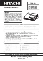
Image 13-12
Schematic overview of the electrical connectors on the Power Distribution Board
-
A:
A colored cable tie (1) is mounted on the formatter cables. This color must correspond with the color of the formatter
connector seats (2).
1
1
1
2
Image 13-13
Color coding of the formatter cables
-
B, C & D
:
1) Each connector group (B, C & D) corresponds with a bunch of wires (with 3 connectors) and represents a speci
fi
c color (B
= red, C = green & D = blue). This color must correspond with the colored cable tie (3) mounted on each bunch of wires.
2) Couple the 3 connectors of each bunch:
fi
rst the biggest connector, then the green and orange connector (according to
the color of the connector seats (4) on the board).
1
3
4
Image 13-14
Connecting the DMD cables
-
E
: The connector seats and wires each have a different color. Couple the corresponding colors.
8. Place the light processor cover on top of the projector (1) so that the hooks (H) on both sides match with the holes (F).
Slide the cover backwards until the hooks slide under the top frame (2).
200
R5905312 HDF W SERIES 24/01/2013
Summary of Contents for HDF W series
Page 1: ...HDF W series Service manual R5905312 01 24 01 2013 ...
Page 4: ......
Page 8: ...Table of contents 4 R5905312 HDF W SERIES 24 01 2013 ...
Page 12: ...1 Safety 8 R5905312 HDF W SERIES 24 01 2013 ...
Page 30: ...3 Preventative maintenance actions 26 R5905312 HDF W SERIES 24 01 2013 ...
Page 35: ...5 Troubleshooting 5 TROUBLESHOOTING R5905312 HDF W SERIES 24 01 2013 31 ...
Page 36: ...5 Troubleshooting 32 R5905312 HDF W SERIES 24 01 2013 ...
Page 110: ...6 Removal and installation of the projector covers 106 R5905312 HDF W SERIES 24 01 2013 ...
Page 111: ...7 Power Input 7 POWER INPUT R5905312 HDF W SERIES 24 01 2013 107 ...
Page 112: ...7 Power Input 108 R5905312 HDF W SERIES 24 01 2013 ...
Page 120: ...7 Power Input 116 R5905312 HDF W SERIES 24 01 2013 ...
Page 172: ...10 Card Cage 168 R5905312 HDF W SERIES 24 01 2013 ...
Page 182: ...11 Lamp Power Supply 178 R5905312 HDF W SERIES 24 01 2013 ...
Page 183: ...12 Start Pulse Generator 12 START PULSE GENERATOR R5905312 HDF W SERIES 24 01 2013 179 ...
Page 184: ...12 Start Pulse Generator 180 R5905312 HDF W SERIES 24 01 2013 ...
Page 192: ...12 Start Pulse Generator 188 R5905312 HDF W SERIES 24 01 2013 ...
Page 242: ...14 Lenses and Lens Holder 238 R5905312 HDF W SERIES 24 01 2013 ...
Page 270: ...15 Liquid cooling circuit 266 R5905312 HDF W SERIES 24 01 2013 ...
Page 274: ...16 Heat exchanger Image 16 5 Remove assembly 270 R5905312 HDF W SERIES 24 01 2013 ...
Page 280: ...16 Heat exchanger Image 16 13 276 R5905312 HDF W SERIES 24 01 2013 ...
Page 309: ...19 Board Diagnostic LED s 19 BOARD DIAGNOSTIC LED S R5905312 HDF W SERIES 24 01 2013 305 ...
Page 310: ...19 Board Diagnostic LED s 306 R5905312 HDF W SERIES 24 01 2013 ...
Page 328: ...19 Board Diagnostic LED s 324 R5905312 HDF W SERIES 24 01 2013 ...