8. Lamp and lamp house
Image 8-20
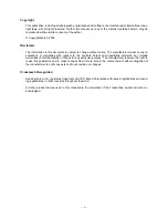
Anode socket installation
7. Reinstall the UV blocker assembly as illustrated. Make sure that the xenon lamp is properly supported by the lamp supporting
mechanism in the centre of the UV blocker. Use the opening at the side of the Lamp House to guide the supporting pin of the
xenon lamp into the anode supporting mechanism.
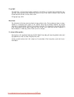
Image 8-21
UV blocker installation
8. Secure the UV blocker by fastening the four retaining thumbscrews as illustrated.
Note:
Please ensure that the thumb screws turning wires are
fl
ush with the cover or interference will occur while inserting the
lamp house into the projector.
Image 8-22
Secure UV blocker
9. Fasten the cathode side of the xenon lamp using a hexagon socket head screw M6 x 40 and a plain washer as illustrated. Use a
torque of
2,5 Nm
(1,84 lbf*ft) to fasten the hexagon socket head screw. Use for that a torque wrench with a 5 mm Allen socket.
Caution:
Make sure that the both pins of the cathode adapter remain engaged in the foreseen slots. Use one hand to keep
the xenon lamp into position while inserting the hexagon socket head screw.
130
R5905312 HDF W SERIES 24/01/2013
Summary of Contents for HDF W series
Page 1: ...HDF W series Service manual R5905312 01 24 01 2013 ...
Page 4: ......
Page 8: ...Table of contents 4 R5905312 HDF W SERIES 24 01 2013 ...
Page 12: ...1 Safety 8 R5905312 HDF W SERIES 24 01 2013 ...
Page 30: ...3 Preventative maintenance actions 26 R5905312 HDF W SERIES 24 01 2013 ...
Page 35: ...5 Troubleshooting 5 TROUBLESHOOTING R5905312 HDF W SERIES 24 01 2013 31 ...
Page 36: ...5 Troubleshooting 32 R5905312 HDF W SERIES 24 01 2013 ...
Page 110: ...6 Removal and installation of the projector covers 106 R5905312 HDF W SERIES 24 01 2013 ...
Page 111: ...7 Power Input 7 POWER INPUT R5905312 HDF W SERIES 24 01 2013 107 ...
Page 112: ...7 Power Input 108 R5905312 HDF W SERIES 24 01 2013 ...
Page 120: ...7 Power Input 116 R5905312 HDF W SERIES 24 01 2013 ...
Page 172: ...10 Card Cage 168 R5905312 HDF W SERIES 24 01 2013 ...
Page 182: ...11 Lamp Power Supply 178 R5905312 HDF W SERIES 24 01 2013 ...
Page 183: ...12 Start Pulse Generator 12 START PULSE GENERATOR R5905312 HDF W SERIES 24 01 2013 179 ...
Page 184: ...12 Start Pulse Generator 180 R5905312 HDF W SERIES 24 01 2013 ...
Page 192: ...12 Start Pulse Generator 188 R5905312 HDF W SERIES 24 01 2013 ...
Page 242: ...14 Lenses and Lens Holder 238 R5905312 HDF W SERIES 24 01 2013 ...
Page 270: ...15 Liquid cooling circuit 266 R5905312 HDF W SERIES 24 01 2013 ...
Page 274: ...16 Heat exchanger Image 16 5 Remove assembly 270 R5905312 HDF W SERIES 24 01 2013 ...
Page 280: ...16 Heat exchanger Image 16 13 276 R5905312 HDF W SERIES 24 01 2013 ...
Page 309: ...19 Board Diagnostic LED s 19 BOARD DIAGNOSTIC LED S R5905312 HDF W SERIES 24 01 2013 305 ...
Page 310: ...19 Board Diagnostic LED s 306 R5905312 HDF W SERIES 24 01 2013 ...
Page 328: ...19 Board Diagnostic LED s 324 R5905312 HDF W SERIES 24 01 2013 ...