Auto Exposure
During Auto Exposure, the exposure
time
and gain are
optimized
for the current
inspection.
Click Start to begin Auto Exposure.
Note: Several triggers may be required to calculate the
optimized
values for exposure and gain.
7.2 Trigger
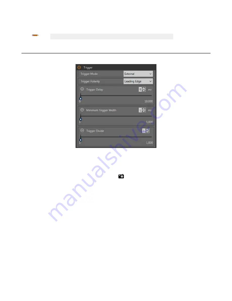
Use the Trigger parameters to set the method and rate at which the sensor captures images. Trigger parameters are stored in the
inspection
file
and can be
different
for each
inspection.
Figure 55. Trigger
Internal (default)
The sensor triggers itself at a
user-defined
rate. Use the slider or enter the desired rate, from 10 ms to 10,000 ms. The default
rate is 100 ms.
External
The sensor is triggered either manually using the trigger
button
in the Vision Manager
software
or it is triggered by an
external source (via the trigger pin), such as a photoelectric sensor. The external trigger
option
has the following parameters:
• Trigger Polarity—Sets when the image is captured compared to the trigger signal. Choose Leading Edge to capture
images at the leading edge of a trigger signal. Choose Trailing Edge to capture images at the trailing edge of the trigger
signal. The default is Leading Edge.
• Trigger Delay—Sets the
fixed
time
from the instant the sensor receives a valid trigger to the instant the sensor
captures the image. Use the slider or enter the desired
time
in milliseconds, from 0 ms to 10,000 ms. The default is 0
ms.
• Minimum Trigger Width—Eliminates unwanted triggers by
accepting
triggers only if they last for a
specified
duration.
Use the slider or enter the desired minimum trigger width in milliseconds, from 1 ms to 5,000 ms. The default is 1 ms.
• Trigger Divide—Sets the logic for how valid trigger inputs are related to actual images taken. If the Trigger Divide is set
to 1, an image is captured in response to every valid trigger. If it is set to 2, an image is captured in response to every
second valid trigger, and so on. Use the slider or enter the desired trigger divide, from 1 to 1,000. The default is 1.
Free Run
The sensor immediately issues a new trigger at the end of an
inspection.
Industrial Ethernet
The Industrial Ethernet
communications
channel controls the trigger. A PLC or HMI triggers the camera tool over an Industrial
Ethernet protocol such as EtherNet/IP or PROFINET.
VE Series Smart Camera
48
www.bannerengineering.com - Tel: 763.544.3164


