86
P/N 133487
Banner Engineering Corp.
•
Minneapolis, U .S .A .
www .bannerengineering .com • Tel: 763 .544 .3164
SC22-3 Safety Controller
Instruction Manual
Appendix A
Each sensor must be routinely inspected and tested per the
manufacturer’s recommendations . Care must be taken not to
exceed operational specifications (e .g ., the maximum number of
switching operations) .
Each sensor must be securely mounted to prevent inadvertent
movement (creeping) or unauthorized removal . Methods include,
but are not limited to, secured edging or trim, tamper-resistant or
one-way fasteners, and recessed flooring or mounting surface, in
addition to the size and weight of large mats .
Each sensor must be installed to minimize tripping hazards
(particularly towards the machine hazard) . A tripping hazard
may exist when the difference in height of an adjacent horizontal
surface is 4 mm (1/8") or more . Tripping hazards must be
minimized at joints, junctions, and edges, and when additional
coverings are used . Methods include a ground-flush installation
of the sensor, or a ramp that does not exceed 20° from
horizontal . Use contrasting colors or markings to identify ramps
and edges .
The safety mat system must be sized and positioned so that
persons cannot enter the hazardous area without being detected,
and can not reach the hazard before the hazardous conditions
have ceased . Additional guards or safeguarding devices may be
required to ensure that exposure to the hazard(s) is not possible
by reaching over, under or around the device’s sensing surface .
A safety mat installation must take into account the possibility of
easily stepping over the sensing surface and not being detected .
ANSI and international standards require a minimum depth of
field of the sensor surface (the smallest distance between the
edge of the mat and hazard) to be from 750 to 1200 mm (30" to
48"), depending on the application and the relevant standard .
The possibility of stepping on machine supports or other
physical objects to bypass or climb over the sensor also must be
prevented .
Safety Mat Separation Distance
As a stand-alone safeguard, the sensor must be installed at a
separation distance (safety distance) so that the exterior edge of
the sensing surface is at or beyond the safety distance, unless
solely used to prevent start/restart or solely used for clearance
safeguarding (see ANSI/RIA R15 .06) .
The separation distance required for an application depends
upon several factors, including the speed of the hand (or
individual), the total system stopping time (which includes
several response time components), and the depth penetration
factor . The user must refer to the relevant standard to determine
the appropriate distance or means to ensure that individuals can
not be exposed to the hazard(s) .
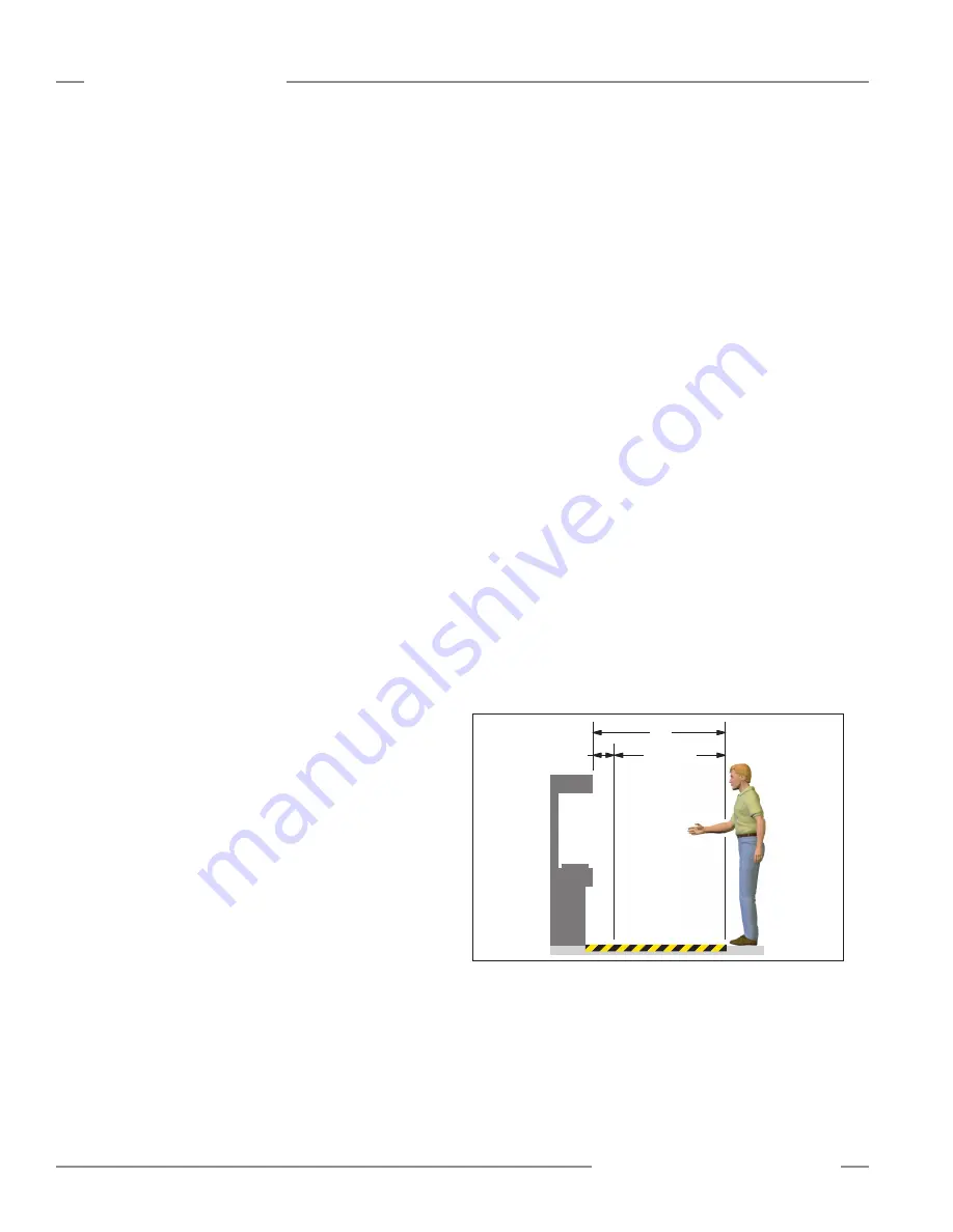
One formula used to calculate separation distance (Ds) is:
Ds = K x (Ts + Tr ) + Dpf
where:
K = the OSHA-recommended hand speed constant of 63" per
second (NOTE below);
Ts = the overall stop time of the machine, measured from
the application of the “stop” signal to the final ceasing
of all motion (including stop times of all relevant control
elements, and measured at maximum machine velocity) .
Tr = the response time of the safety mat system: the response
time of the sensor(s), as stated by the manufacturer, plus
the response time of the Safety Controller as measured
from the time a stop is signalled by the safety mat, after
it was stepped on . (Controller default response is 0 .010
seconds, plus any additional closed-to-open debounce
time . If the debounce time is adjusted, the time in excess
of 6 ms (=default closed-to-open debounce time) must
be added to the stated response; refer to Specifications,
Section 2 .2 .)
Dpf = the added distance due to depth penetration factor:
1 .2 m (48")
NOTE: The OSHA-recommended hand-speed constant (K) has
been determined by various studies, and although these
studies indicate speeds of 63"/second to more than
100"/second, they are not conclusive determinations .
The employer should consider all factors, including the
physical ability of the operator, when determining the
value of K to be used .
Hazardous
Zone
or
Area
Safety Mat
Ds
K(Ts + Tr)
Dpf
Figure A-5. Determining safety distance (Ds) for the safety mat
If an individual can cross completely over the sensor and no
longer be detected, supplemental safeguarding or other means
should be used to prevent unexpected startup and exposure to
a hazard . At a minimum, the safety mat system (or the machine
control) must be manually reset and require re-initiation of
the normal actuating means prior to the start or re-start of the
machine cycle .


