70
P/N 133487
Banner Engineering Corp.
•
Minneapolis, U .S .A .
www .bannerengineering .com • Tel: 763 .544 .3164
SC22-3 Safety Controller
Instruction Manual
Troubleshooting and Maintenance
8.4 Recovering from a Lockout
To recover from a lockout condition:
1 . Follow the recommendation in the fault display (for example,
Cycle Input) .
2 . Follow the recommended steps and checks listed under
Further Steps and Checks in the troubleshooting table
(Section 8 .3 .1) .
3 . Perform a system reset .
4 . Cycle the power and perform a system reset if needed
If these steps do not remedy the lockout condition, contact the
factory (see Section 8 .2) .
8.5 Fault Diagnostics — PCI
The first step in diagnosing faults via the PCI is to bring up the
Live Display screen (see Section 6 .1) .
The Live Display screen (if the PC is connected to the
Controller) shows in real time, the status of each safety output,
which device caused an output to turn OFF, if any, and basic
information about the Controller model and the configuration
(see Figure 6-1) .
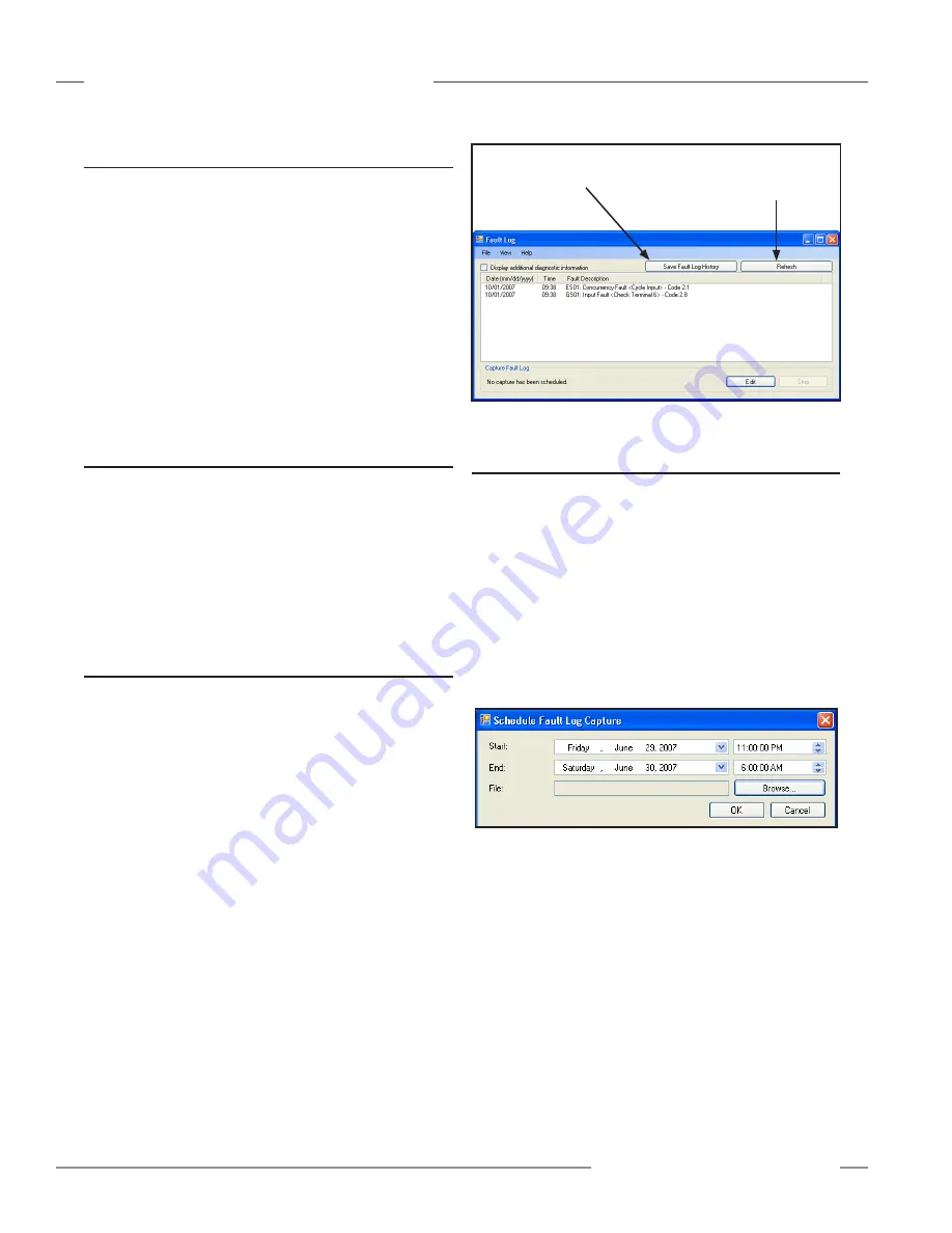
8.5.1 Fault Log — PCI
While the Controller is powered up and connected to the
PC, every fault that occurs is stored in the fault log . The PCI
displays real-time fault information via the Fault Log screen
shown in Figure 8-1 . The fault information includes the following
information about each fault; expand the size of the window as
needed to see all the faults .
• Date and time of the fault
• Device name
• General description of the fault, and
• Fault code (for lookup table reference) .
Additional code information can be displayed, should factory
applications assistance be required .
Figure 8-1. Fault Log screen — PCI
Clears the faults displayed and gets
the latest faults stored in the Safety
Controller’s fault log.
Saves the displayed faults
to a file for later reference.
8.5.2 Fault Log Recording — PCI
To determine the cause of a persistent fault, compile an
extended record of the faults and save it to a file . Select the Edit
button in the Fault Log screen (Figure 8-1) to establish the times
at which the fault data record starts and stops . The Schedule
Fault Log Capture menu (Figure 8-2) will then appear .
The menu settings below show that any fault that occurs from
Friday, June 29, 2007 at 11:00 pm until Saturday, June 30, 2007
at 6:00 am will be recorded to a user-designated file for future
reference . (NOTE: The selected start and stop times must be
later than the time at which this selection is made; the fault log
capture will not capture past faults .)
Figure 8-2. Schedule Fault Log Capture menu


