38
P/N 133487
Banner Engineering Corp.
•
Minneapolis, U .S .A .
www .bannerengineering .com • Tel: 763 .544 .3164
SC22-3 Safety Controller
Instruction Manual
Configuration — PC Interface
Once an input device is selected, the Properties menu for that
device pops up . This menu presents the properties that must
be established for each type of input device . The user-defined
properties include (depending on the device):
• Name — The name (or ciruit designation) of each specific
device (not device type)
• Circuit Type — A list of the types of contact or solid-state
circuits that can be used for that device type
• Reset Logic — Automatic (Trip mode) and Manual (Latch
mode) options for that device
• Input Terminal Assignment — These are assigned automatically
but can be changed to any unused input terminal .
• I/O map — Establishes relationships between input devices and
outputs
NOTE: Input device properties and functions are discussed in
Section 3 .2 and Appendix A .
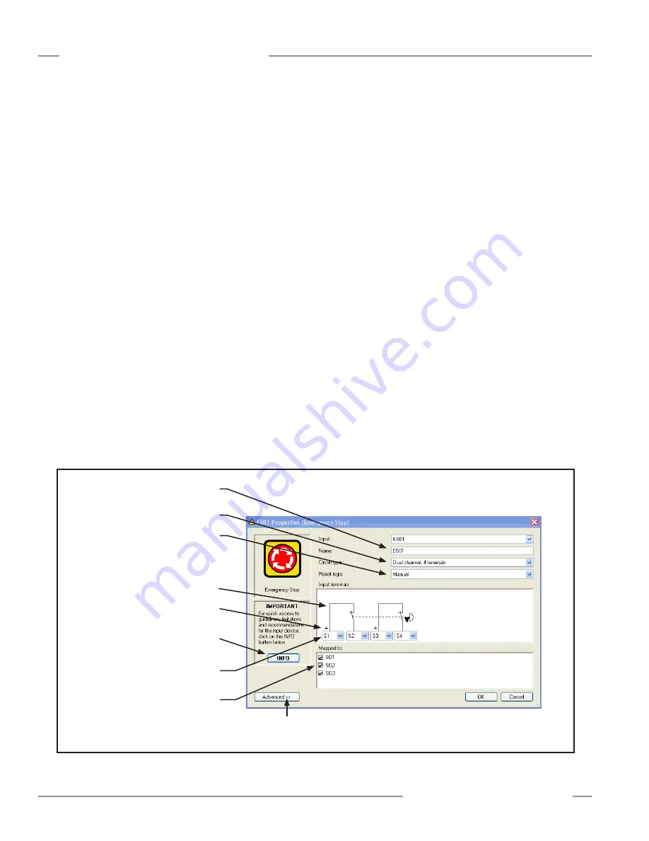
Follow the configuration steps as they appear on the screen (see
Figure 4-7) .
Name: Change the name to something meaningful to you, such
as: E-STOP1 . Any input device can be renamed during the
configuration process .
Circuit Type: Select the appropriate circuit type from the drop-
down menu for your device . The selected circuit type will appear
in the input terminals diagram, with automatically assigned
terminal numbers; the terminal numbers can be reassigned using
the drop-down menus . The plus signs at S13 and S15 (see
Figure 4-7) designate that these terminals supply the +24V dc
source for the device contacts .
NOTE: See Appendix A for more information about safety
circuit integrity levels and the capabilities of each
circuit type.
Reset Logic: Select between Manual or Automatic Reset from
the drop-down menu .
Mapping: Map each safety input device to one or more safety
outputs (at least one must be selected) by checking or un-
checking the boxes . (Just click on a box to select or deselect it .)
If the safety input device is a muting sensor, a bypass switch, or
a mute enable sensor, map those inputs to at least one of the
other safety input devices .
When a safety input device with manual reset is added, a new
window automatically appears to add a reset input device for that
device . Any safety input device which keeps the default Manual
reset logic setting requires a reset for any safety output mapped
to that device . A separate reset may be assigned for each safety
output .
The wiring diagram will begin to populate with your chosen
device(s), as will the ladder logic diagram and configuration
summary .
Figure 4-7. Safety Input Device Properties screen
Use the drop-down menus to change the
terminal assignments
Map each device to any
1, 2, or 3 safety outputs
Type in a name for the device
Select a circuit type from the
drop-down menu
Select the reset logic from
the drop-down menu
Depicts the selected circuit type
and terminal assignments
+ indicates the terminal that supplies
the +24V dc source for the device
Info button directs you to the
appropriate section in Appendix A.
Advanced settings are dependent on device
type (e.g., debounce time settings)


