P/N 133487
103
Banner Engineering Corp.
•
Minneapolis, U .S .A .
www .bannerengineering .com • Tel: 763 .544 .3164
SC22-3 Safety Controller
Instruction Manual
Appendix B
B.5 Create a Configuration
• Click on the System Settings icon
on the right-hand
side of the tool bar .
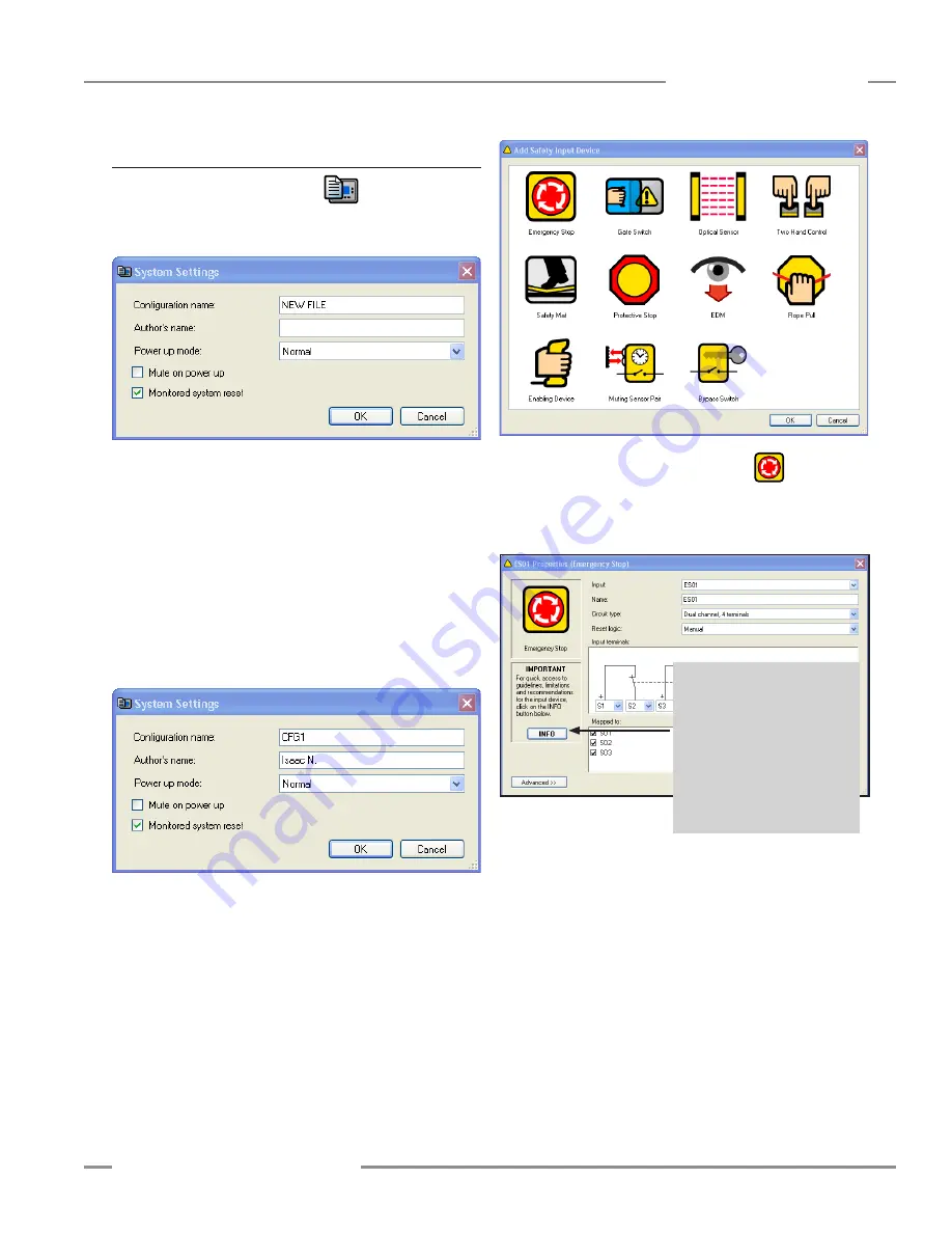
The pop-up System Settings menu will appear .
• Name the configuration file CFG1 . (Up to 16 alphanumeric
characters may be used .)
• Add your name in the Author’s name box . (Up to 10
alphanumeric characters may be used; abbreviate as needed .)
• Keep the default settings listed below .
Power up mode: Normal
Mute on power up: No check mark
Monitored system reset: Check mark (click on the checkbox
to select or deselect it .)
Your System Settings menu should look like this:
• Click OK .
Add an E-Stop Button Input
• Click on the Wiring Diagram tab, if the wiring diagram is not
already displayed on the screen .
• Click on the Add Safety Input button in the center of the tool
bar . The Add Safety Input Device pop-up menu will appear .
Select Emergency Stop Button Properties
• Double-click on the Emergency Stop icon
in the Add
Safety Input device menu . The ES01 Properties menu will
appear . (Abbreviated, sequentially numbered device names are
automatically assigned but can be changed .)
• Name: Keep ES01 .
• Circuit type: Keep the Dual-channel, 4-terminal . (Use the
drop-down Circuit Type field to see other circuit
options .)
• Reset logic: Keep the default Manual .
• Map to: Keep the ES01 mapped to all three safety outputs
(SO1, SO2, SO3) .
• Click OK .
Because a manual reset signal was chosen for the E-stop button,
when OK is selected and the ES01 Properties menu closes, the
RS01 Properties Manual Reset screen will appear automatically .
Helpful Hint: If you want to
access more information about
a device and which circuit types
provide what level of safety,
click on the Info button . It will
immediately bring up the section
from Appendix A of this manual
that provides that information for
the displayed input device .


